Nissan Maxima Service and Repair Manual: Main line between ADP and DLC circuit
Diagnosis Procedure
1.CHECK CONNECTOR
- Turn the ignition switch OFF.
- Disconnect the battery cable from the negative terminal.
- Check the following terminals and connectors for damage, bend and
loose connection (connector side
and harness side).
- Harness connector B1
- Harness connector M6
2.CHECK HARNESS CONTINUITY (OPEN CIRCUIT)
- Disconnect the following harness connectors.
- Harness connectors B208 and B32
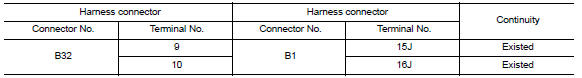
- Harness connectors B1 and M6
- Check the continuity between the harness connectors.
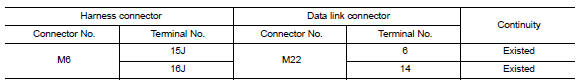
3.CHECK HARNESS CONTINUITY (OPEN CIRCUIT)
Check the continuity between the harness connector and the data link connector.

 v DLC and HVAC circuit
Diagnosis Procedure
1.CHECK HARNESS CONTINUITY (OPEN CIRCUIT)
Turn the ignition switch OFF.
Disconnect the battery cable from the negative terminal.
Disconnect the following harness connector ...
Other materials:
Front washer
WASHER TUBE
WASHER TUBE : Layout
Washer nozzle (LH)
Washer nozzle hose (LH)
Washer nozzle (RH)
Washer nozzle hose (RH)
Y-tube connector
Washer tank hose
Washer tank
Tube connectors
Clip
FRONT WASHER NOZZLE
FRONT WASHER NOZZLE : Removal and Installation
REMOVAL
...
Cup holders
Front cup holders
CAUTION
Avoid abrupt starting and braking when
the cup holder is being used to prevent
spilling the drink. If the liquid is hot, it
can scald you or your passenger. Spilled
liquid can also damage the seat climate
system.
Use only soft cups in the cup holder.
...
Configuration (BCM)
CONFIGURATION (BCM) : Description
Vehicle specification needs to be written with CONSULT because it is not
written after replacing BCM.
Configuration has three functions as follows
Function
Description
"Before Replace ECU "
Reads the vehi ...
Nissan Maxima Owners Manual
- Illustrated table of contents
- Safety-Seats, seat belts and supplemental restraint system
- Instruments and controls
- Pre-driving checks and adjustments
- Monitor, climate, audio, phone and voice recognition systems
- Starting and driving
- In case of emergency
- Appearance and care
- Do-it-yourself
- Maintenance and schedules
- Technical and consumer information
Nissan Maxima Service and Repair Manual

0.0067