Nissan Maxima Service and Repair Manual: v DLC and HVAC circuit
Diagnosis Procedure
1.CHECK HARNESS CONTINUITY (OPEN CIRCUIT)
- Turn the ignition switch OFF.
- Disconnect the battery cable from the negative terminal.
- Disconnect the following harness connectors.
- ECM
- A/C auto amp.
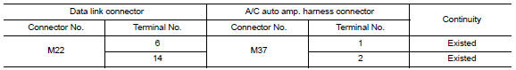
- Check the continuity between the data link connector and the A/C auto amp. harness connector.
 Main line between ADP and DLC circuit
Diagnosis Procedure
1.CHECK CONNECTOR
Turn the ignition switch OFF.
Disconnect the battery cable from the negative terminal.
Check the following terminals and connectors for damage, bend and ...
 Main line between HVAC and ABS circuit
Diagnosis Procedure
1.CHECK CONNECTOR
Turn the ignition switch OFF.
Disconnect the battery cable from the negative terminal.
Check the following terminals and connectors for damage, bend and ...
Other materials:
HVAC branch line circuit
Diagnosis Procedure
1.CHECK CONNECTOR
Turn the ignition switch OFF.
Disconnect the battery cable from the negative terminal.
Check the terminals and connectors of the A/C auto amp. for
damage, bend and loose connection (unit
side and connector side).
2.CHECK HARNESS FOR OPEN CIRCUI ...
Fuel pump
Description
*: ECM determines the start signal status by the signals of engine speed and
battery voltage.
The ECM activates the fuel pump for several seconds after the ignition switch is
turned ON to improve engine
start ability. If the ECM receives a engine speed signal from the camsh ...
Precaution
PRECAUTIONS
Precaution for Supplemental Restraint System (SRS) "AIR
BAG" and "SEAT BELT
PRE-TENSIONER"
The Supplemental Restraint System such as "AIR BAG" and
"SEAT BELT PRE-TENSIONER", used along
with a front seat belt, helps to reduce the risk or severity of injury to the
driver and fr ...
Nissan Maxima Owners Manual
- Illustrated table of contents
- Safety-Seats, seat belts and supplemental restraint system
- Instruments and controls
- Pre-driving checks and adjustments
- Monitor, climate, audio, phone and voice recognition systems
- Starting and driving
- In case of emergency
- Appearance and care
- Do-it-yourself
- Maintenance and schedules
- Technical and consumer information
Nissan Maxima Service and Repair Manual

0.0061