Nissan Maxima Service and Repair Manual: Power supply and ground circuit
Description
EPS system functions by ignition power supply.
Diagnosis Procedure
1.CHECK POWER SUPPLY
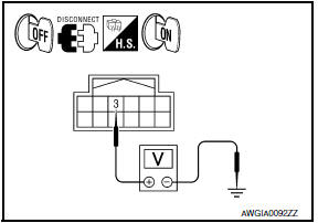
- Turn the ignition switch OFF.
- Disconnect power steering control unit connector.
- Turn the ignition switch ON.
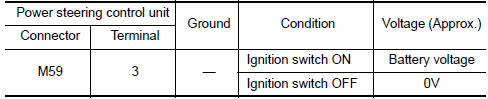
- Check voltage between power steering control unit connector
M59 terminal 3 and ground.
2.CHECK GROUND CIRCUIT
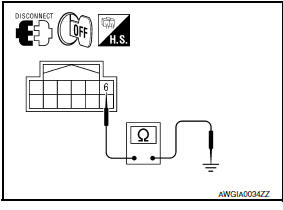
- Turn the ignition switch OFF.
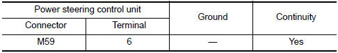
- Check continuity between power steering control unit connector
M59 terminal 6 and ground.
3.CHECK TERMINALS AND HARNESS CONNECTORS
Check power steering control unit pin terminals for damage or loose connection with harness connector.

 Power steering solenoid valve
Description
Power steering solenoid valve controls the power steering oil pressure in the
gear housing assembly.
Diagnosis Procedure
1.CHECK POWER STEERING SOLENOID VALVE SIGNAL
Start eng ...
Other materials:
System maintenance
The sensor A is located behind the lower grille
of the front bumper.
To keep the system operating properly, be sure to
observe the following:
Always keep the sensor area of the front
bumper clean.
Do not strike or damage the areas around
the sensor.
Do not cover or attach st ...
Precaution
Precaution for Supplemental Restraint System (SRS) "AIR BAG" and
"SEAT BELT PRE-TENSIONER"
The Supplemental Restraint System such as "AIR BAG" and "SEAT BELT
PRE-TENSIONER", used along with a front seat belt, helps to reduce the risk
or severity of injury to the driver and front passenger for ...
Remove
Use the following procedure to remove the head
restraint/headrest:
1. Pull the head restraint/headrest up to the
highest position.
2. Push and hold the lock knob.
3. Remove the head restraint/headrest from
the seat.
4. Store the head restraint/headrest properly in
a secure place so i ...
Nissan Maxima Owners Manual
- Illustrated table of contents
- Safety-Seats, seat belts and supplemental restraint system
- Instruments and controls
- Pre-driving checks and adjustments
- Monitor, climate, audio, phone and voice recognition systems
- Starting and driving
- In case of emergency
- Appearance and care
- Do-it-yourself
- Maintenance and schedules
- Technical and consumer information
Nissan Maxima Service and Repair Manual

0.0061