Nissan Maxima Service and Repair Manual: Power steering solenoid valve
Description
Power steering solenoid valve controls the power steering oil pressure in the gear housing assembly.
Diagnosis Procedure
1.CHECK POWER STEERING SOLENOID VALVE SIGNAL
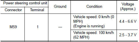
- Start engine.
- Check voltage between power steering control unit connector
M59 terminal 1 and ground
2.CHECK HARNESS BETWEEN POWER STEERING SOLENOID VALVE AND POWER STEERING CONTROL UNIT FOR OPEN
- Turn ignition switch OFF.
- Disconnect power steering solenoid valve connector.
- Disconnect power steering control unit connector.
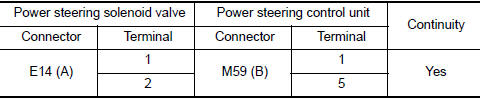
- Check continuity between power steering solenoid valve connector
E14 (A) terminals 1, 2 and power steering control unit
connector M59 (B) terminal 1, 5.
3.CHECK HARNESS BETWEEN POWER STEERING SOLENOID VALVE AND POWER STEERING CONTROL UNIT FOR SHO
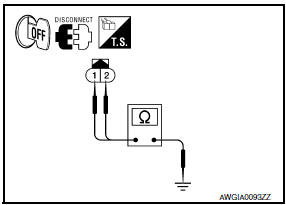
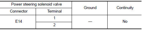
- Check continuity between power steering solenoid valve connector
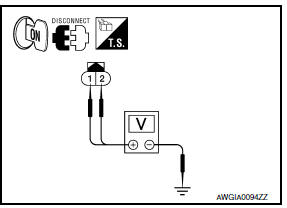
E14 terminals 1, 2 and ground. - Turn ignition switch ON.
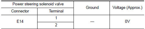
- Check voltage between power steering solenoid valve connector
E14 terminals 1, 2 and ground.
4.CHECK POWER STEERING SOLENOID VALVE
Perform power steering solenoid valve component inspection.
5.CHECK TERMINALS AND HARNESS CONNECTORS
- Check power steering control unit pin terminals for damage or loose connection with harness connector.
- Check power steering solenoid valve pin terminals for damage or loose connection with harness connector.
Component Ins
1.POWER STEERING SOLENOID VALVE RESISTANCE CHECK
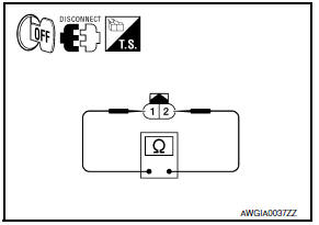
- Turn ignition switch OFF.
- Disconnect power steering solenoid valve connector.
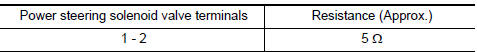
- Check resistance between power steering solenoid valve terminals
1 and 2
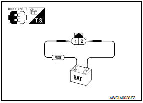
Check power steering solenoid valve by listening for its operation
sound
while applying battery voltage to power steering solenoid
valve terminal 1
(positive) and battery ground to terminal 2 (negative).
 Power supply and ground circuit
Description
EPS system functions by ignition power supply.
Diagnosis Procedure
1.CHECK POWER SUPPLY
Turn the ignition switch OFF.
Disconnect power steering control unit connector.
Turn th ...
 Engine speed signal circuit
Description
ECM sends engine speed signal to power steering control unit.
Diagnosis Procedure
1.PERFORM ECM SELF-DIAGNOSIS
With CONSULT
Perform ECM self-diagnosis.
2.CHECK HARNESS BETWEEN ECM AN ...
Other materials:
Trouble diagnosis - specification value
Description
The specification (SP) value indicates the tolerance of the value that is
displayed in "SPEC" of "DATA MONITOR"
mode of CONSULT during normal operation of the Engine Control System. When the
value in "SPEC" in
"DATA MONITOR" mode is NOT within the SP value, the Engine Control Sy ...
The oil pressure warning lamp does not turn off
Description
The oil pressure warning lamp remains illuminated while
the engine is running (normal oil pressure).
Diagnosis Procedure
Regarding Wiring Diagram information, refer to MWI-87,
"Wiring Diagram".
1.CHECK OIL PRESSURE WARNING LAMP
Perform IPDM E/R auto active test. Refer to PCS-11, ...
Windshield-washer fluid
Windshield-washer fluid reservoir
Fill the windshield-washer fluid reservoir periodically.
Add windshield-washer fluid when the low
windshield-washer fluid warning light comes on.
To fill the windshield-washer fluid reservoir, lift
the cap off the reservoir and pour the windshieldwasher ...
Nissan Maxima Owners Manual
- Illustrated table of contents
- Safety-Seats, seat belts and supplemental restraint system
- Instruments and controls
- Pre-driving checks and adjustments
- Monitor, climate, audio, phone and voice recognition systems
- Starting and driving
- In case of emergency
- Appearance and care
- Do-it-yourself
- Maintenance and schedules
- Technical and consumer information
Nissan Maxima Service and Repair Manual

0.0061