Nissan Maxima Service and Repair Manual: Tweeter
Description
The audio unit sends audio signals to the BOSE speaker amp. The BOSE speaker amp. amplifies the audio signals before sending them to the tweeters using the audio signal circuits.
Diagnosis Procedure
1.CONNECTOR CHECK
Check the audio unit, BOSE speaker amp. and speaker connectors for the following:
- Proper connection
- Damage
- Disconnected or loose terminals
2.HARNESS CHECK
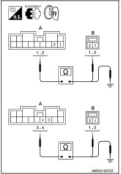
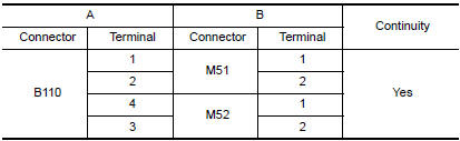
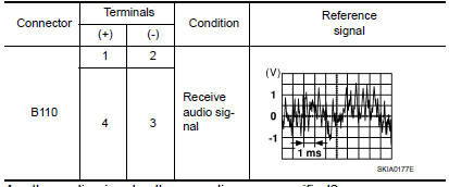
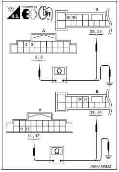
- Disconnect BOSE speaker amp. connector B110 and suspect tweeter connector.
- Check continuity between BOSE speaker amp. harness connector B110 (A) and suspect tweeter harness connector (B).
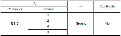
- Check continuity between BOSE speaker amp. harness connector B110 (A) and ground.
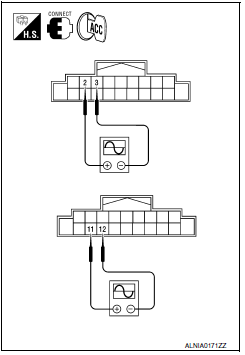
3.TWEETER SIGNAL CHECK
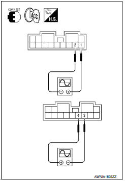
- Connect BOSE speaker amp. connector B110 and suspect tweeter connector.
- Turn ignition switch to ACC.
- Push POWER switch.
- Check the signal between BOSE speaker amp. harness connector B110 terminals with CONSULT or oscilloscope.
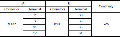
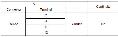
4.HARNESS CHECK
- Disconnect audio unit connector M132 and BOSE speaker amp.
connector B109.
- Check continuity between audio unit harness connector M132 (A) and BOSE speaker amp. harness connector B109 (B).
- Check continuity between audio unit harness connector M132 (A) and ground.
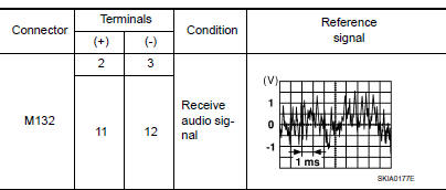
5.TWEETER SIGNAL CH
- Connect audio unit connector and BOSE speaker amp. connector.
- Turn ignition switch ACC.
- Push POWER switch.
- Check the signal between audio unit harness connector terminals with CONSULT or oscilloscope
 Front door speaker
Description
The audio unit sends audio signals to the BOSE speaker amp. The BOSE speaker
amp. amplifies the audio signals before sending them to the front door
speakers using the audio signal cir ...
 Center speaker
Description
The audio unit sends audio signals to the BOSE speaker amp. The BOSE speaker
amp. amplifies the audio signals before sending them to the center speaker
using the audio signal circuits ...
Other materials:
Tel antenna
Removal and Installation
REMOVAL
Disconnect the battery negative terminal. Refer to PG-67, "Removal
and Installation (Battery)".
Remove the rear parcel shelf finisher. Refer to INT-28, "Removal
and Installation".
Remove the Bluetooth antenna screw (A).
Detach the Bluetooth antenna ...
AV control unit
Removal and Installation
AV control unit
AV control unit bracket (LH)
AV control unit bracket (RH)
A/C auto amp.
Cluster lid C (with A/C and AV switch
assembly attached)
Clip
AV CONTROL UNIT
Removal
CAUTION:
Before replacing AV control unit, perform "READ CONFIGU ...
RGB digital image signal circuit
Description
Transmit the image displayed with AV control unit with RGB digital image
signal to the display unit.
Diagnosis Procedure
1.CHECK CONTINUITY RGB DIGITAL IMAGE SIGNAL CIRCUIT
Turn ignition switch OFF.
Disconnect display unit connector M151 and AV control unit
connector
...
Nissan Maxima Owners Manual
- Illustrated table of contents
- Safety-Seats, seat belts and supplemental restraint system
- Instruments and controls
- Pre-driving checks and adjustments
- Monitor, climate, audio, phone and voice recognition systems
- Starting and driving
- In case of emergency
- Appearance and care
- Do-it-yourself
- Maintenance and schedules
- Technical and consumer information
Nissan Maxima Service and Repair Manual

0.0069