Nissan Maxima Service and Repair Manual: Front door speaker
Description
The audio unit sends audio signals to the BOSE speaker amp. The BOSE speaker amp. amplifies the audio signals before sending them to the front door speakers using the audio signal circuits.
Diagnosis Procedure
1.CONNECTOR CHECK
Check the audio unit, BOSE speaker amp. and speaker connectors for the following:
- Proper connection
- Damage
- Disconnected or loose terminals
2.HARNESS CHECK
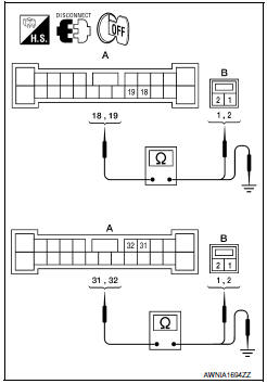
- Disconnect BOSE speaker amp. connector B109 and suspect speaker connector.
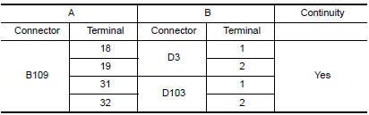
- Check continuity between BOSE speaker amp. harness connector B109 (A) and suspect speaker harness connector (B).
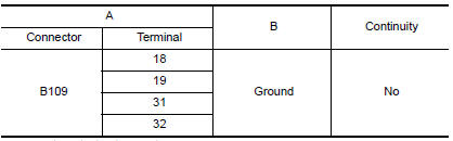
- Check continuity between BOSE speaker amp. harness connector B109 (A) and ground.
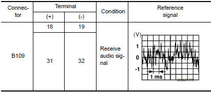
3.FRONT DOOR SPEAKER SIGNAL CHECK
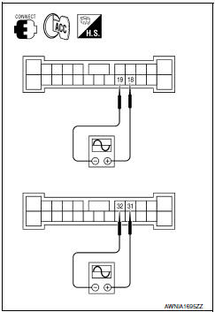
- Connect BOSE speaker amp. connector B109 and suspect speaker connector.
- Turn ignition switch to ACC.
- Push POWER switch.
- Check the signal between BOSE speaker amp. harness connector B109 terminals with CONSULT or oscilloscope.
4.HARNESS CHECK
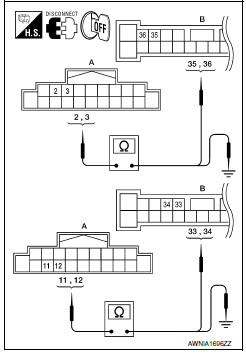
- Disconnect audio unit connector M132 and BOSE speaker amp.
connector B109.
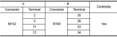
- Check continuity between audio unit harness connector M132 (A) and BOSE speaker amp. harness connector B109 (B).
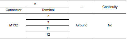
- Check continuity between audio unit harness connector M132 (A) and ground.
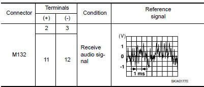
5.FRONT DOOR SPEAKER SIGNAL CHECK
- Connect audio unit connector and BOSE speaker amp. connector.
- Turn ignition switch ACC.
- Push POWER switch.
- Check the signal between audio unit harness connector terminals with CONSULT or oscilloscope.
 Power supply and ground circuit
AUDIO UNIT
AUDIO UNIT : Diagnosis Procedure
1.CHECK FUSES
2.POWER SUPPLY CIRCUIT CHECK
Disconnect audio unit connector M132.
Check voltage between the audio unit connector M132 and grou ...
 Tweeter
Description
The audio unit sends audio signals to the BOSE speaker amp. The BOSE speaker
amp. amplifies the audio signals before sending them to the tweeters using
the audio signal circuits.
Dia ...
Other materials:
Basic inspection
INSPECTION AND ADJUSTMENT
Operational Check
DESCRIPTION
The purpose of the operational check is to check that the individual system
operates normally.
Conditions: Engine running at normal operating temperature
INSPECTION PROCEDURE
1.CHECK MEMORY FUNCTION
Start the engine.
Operate the t ...
Vehicle identification number (VIN) plate
The vehicle identification number (VIN) plate is
attached as shown. This number is the identification
for your vehicle and is used in the vehicle
registration.
Vehicle identification number (chassis number)
The vehicle identification number is located as
shown.
Engine serial number
...
P0868 transmission fluid pressure
Description
The secondary pressure solenoid valve regulates the
secondary pressure to suit the driving condition in
response to a signal sent from the TCM.
DTC Logic
DTC DETECTION LOGIC
DTC CONFIRMATION PROCEDURE
CAUTION:
Always drive vehicle at a safe speed.
NOTE:
Immediately after ...
Nissan Maxima Owners Manual
- Illustrated table of contents
- Safety-Seats, seat belts and supplemental restraint system
- Instruments and controls
- Pre-driving checks and adjustments
- Monitor, climate, audio, phone and voice recognition systems
- Starting and driving
- In case of emergency
- Appearance and care
- Do-it-yourself
- Maintenance and schedules
- Technical and consumer information
Nissan Maxima Service and Repair Manual

0.0059