Nissan Maxima Service and Repair Manual: Power supply and ground circuit
AUDIO UNIT
AUDIO UNIT : Diagnosis Procedure
1.CHECK FUSES
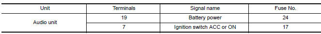
2.POWER SUPPLY CIRCUIT CHECK
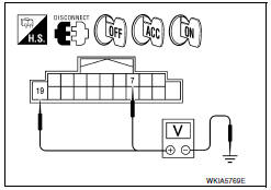
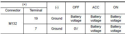
- Disconnect audio unit connector M132.
- Check voltage between the audio unit connector M132 and ground.
3.GROUND CIRCUIT CHECK
Inspect audio unit case ground.
DISPLAY UNIT
DISPLAY UNIT : Diagnosis Procedure
1.CHECK FUSES
Check that the following fuses are not blown.
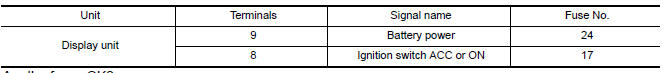
2.POWER SUPPLY CIRCUIT CHECK
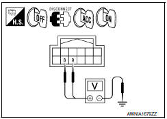
- Turn ignition switch OFF.
- Disconnect display unit connector.
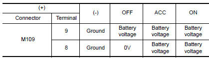
- Check voltage between the display unit and ground.
3.GROUND CIRCUIT CHECK
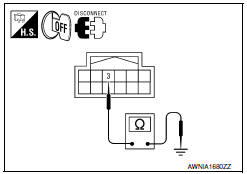
- Turn ignition switch OFF.
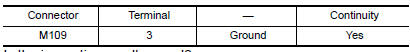
- Check continuity between display unit harness connector and ground.
BOSE SPEAKER AMP
BOSE SPEAKER AMP : Diagnosis Procedure
1.CHECK FUSE
Check for blown fuses.
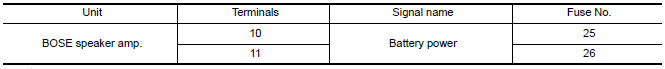
2.CHECK POWER SUPPLY CIRCUIT
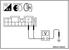
- Turn ignition switch OFF.
- Disconnect BOSE speaker amp connector.
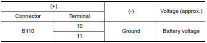
- Check voltage between BOSE speaker amp harness connector and ground.
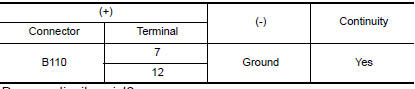
3.CHECK GROUND CIRCUIT
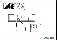
Check continuity between BOSE speaker amp harness connector and ground.
BLUETOOTH CONTROL UNIT
BLUETOOTH CONTROL UNIT : Diagnosis Procedure
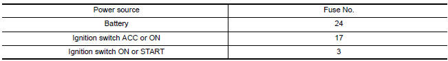
1.CHECK FUSE
Check that the following fuses of the Bluetooth control unit are not blown.
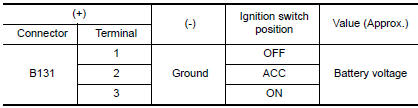
2.CHECK POWER SUPPLY CIRCUIT
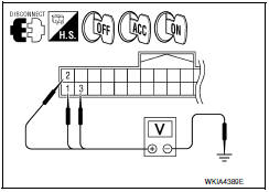
Check voltage between Bluetooth control unit harness connector and ground.
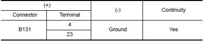
3.CHECK GROUND CIRCUIT

- Turn ignition switch OFF.
- Disconnect Bluetooth control unit connector B131.
- Check continuity between Bluetooth control unit harness connector and groun
MICROPHONE
MICROPHONE : Diagnosis Procedure
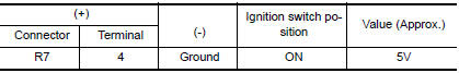
1.CHECK POWER SUPPLY CIRCUIT (MICROPHONE SIDE)
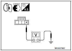
Check voltage between microphone harness connector and ground
2.CHECK POWER SUPPLY CIRCUIT (CONTINUITY)
- Turn ignition switch OFF.
- Disconnect Bluetooth control unit and microphone connectors.
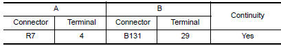
- Check continuity between microphone harness connector R7 (A) terminal 4 and Bluetooth control unit harness connector B131 (B) terminal 29.
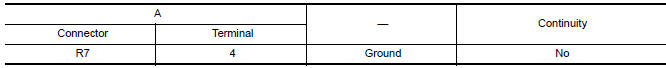
- Check continuity between microphone harness connector R7 (A) terminal 4 and ground.
3.CHECK GROUND CIRCUIT
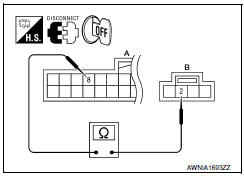
- Turn ignition switch OFF.
- Disconnect Bluetooth control unit and microphone connectors.
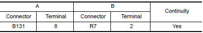
- Check continuity between Bluetooth control unit harness connector B131 (A) terminal 8 and microphone harness connector R7 (B) terminal 2.

 Front door speaker
Description
The audio unit sends audio signals to the BOSE speaker amp. The BOSE speaker
amp. amplifies the audio signals before sending them to the front door
speakers using the audio signal cir ...
Other materials:
Headlights
Replacing the halogen headlight bulb
(if so equipped)
The headlight is a semi-sealed beam type which
uses a replaceable headlight (halogen) bulb.
They can be replaced from inside the engine
compartment without removing the headlight assembly.
If headlight bulb replacement is required, it i ...
Unit disassembly and assembly
CENTER CONSOLE ASSEMBLY
Exploded View
Center console side finisher (LH)
Center console finisher
CVT finisher
Center console storage bin
Center console screw cover (LH)
Center console rear finisher
Center console screw cover (RH)
Center console
Center console lid assembly
...
Oil
Description
MAINTENANCE OF OIL LEVEL
The compressor oil is circulating in the system together with the
refrigerant. It is necessary to fill compressor with oil when replacing A/C
system parts or when a large amount of refrigerant leakage is detected. It is
important to always maintain oil le ...
Nissan Maxima Owners Manual
- Illustrated table of contents
- Safety-Seats, seat belts and supplemental restraint system
- Instruments and controls
- Pre-driving checks and adjustments
- Monitor, climate, audio, phone and voice recognition systems
- Starting and driving
- In case of emergency
- Appearance and care
- Do-it-yourself
- Maintenance and schedules
- Technical and consumer information
Nissan Maxima Service and Repair Manual

0.0071