Nissan Maxima Service and Repair Manual: Entry assist function
ENTRY ASSIST FUNCTION : System Diagram
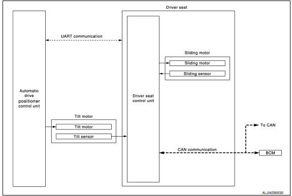
ENTRY ASSIST FUNCTION : System Description
OUTLINE
The seat is in the exiting position when either following condition is satisfied, the seat returns from exiting position to the previous driving position.
NOTE:
- This function is set to OFF before delivery (initial setting).
- Further information for the system setting procedure. Refer to Owner's Manual.
OPERATION PROCEDURE
- Turn the ignition switch to ACC.
- Front seat LH and steering column will return from the exiting position to entry position.
OPERATION CONDITION
Satisfy all of the following items. The entry assist function is not performed if these items are not satisfied.
| Item | Request status |
| Seat, steering column | The vehicle is not moved after performing the exit assist function. |
|
Switch inputs
|
OFF (Not operated) |
| CVT selector lever | P position |
DETAIL FLOW
| Order | Input | Output | Control unit condition |
| 1 | Door switch/Ignition | - | Driver seat control unit receives the signals of ignition switch signal and front door switch from BCM via CAN communication |
| 2 | - | Motors (sliding, tilt) | Driver seat control unit operates the sliding motor when the operating conditions are satisfied and requests the operation of tilt motor to automatic drive positioner control unit via UART communication. The automatic drive positioner control unit operates the tilt motor |
| Sensors (sliding, tilt) | - | Each sensor monitors the operating positions of seat and steering column, then stops the operation of motor when each part reaches the recorded address |
ENTRY ASSIST FUNCTION : Component Parts Location
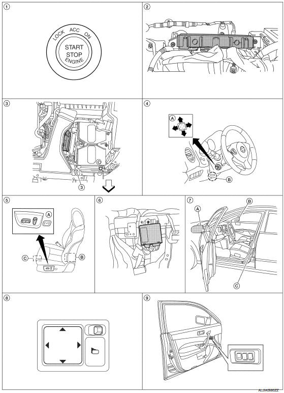
- Push-button ignition switch M38
- BCM M16, M17, M18, M19 (view with instrument panel removed)
- TCM F15
- A. ADP steering switch M39
B. Tilt motor M71, telescopic motor M73 - A. Power seat switch LH B213
B. Reclining motor B222
C. Driver seat control unit B203, B211 - Automatic drive positioner control unit M63, M67 (view with instrument panel removed)
- A. Door mirror LH D4
B. Door mirror RH D107
C. Front door switch LH B8 - Door mirror remote control switch M108
- Seat memory switch D13
: Front
ENTRY ASSIST FUNCTION : Component Description
CONTROL UNITS
| Item | Function |
| Driver seat control unit |
According to the ignition signal and front door switch LH signal from BCM,
|
| Automatic drive positioner control unit | Operates the tilt motor with the instructions from the driver seat control unit. |
| BCM |
Recognizes the following status and transmits it to the driver seat control unit via CAN communication.
|
INPUT PARTS
Switches
| Item | Function |
| Front door switch LH | Detect front door LH open/close status. |
Sensors
| Item | Function |
| Tilt sensor | Detect the up/down position of steering column. |
| Sliding sensor | Detect the front/rear position of seat. |
OUTPUT PARTS
| Item | Function |
| Tilt motor | Move the steering column up/down. |
| Sliding motor | Slide the seat forward/back |
 Exit assist function
EXIT ASSIST FUNCTION : System Diagram
EXIT ASSIST FUNCTION : System Description
OUTLINE
When exiting, if the conditions are satisfied, the seat is moved backward
from normal sitting position ...
 Intelligent key interlock function
INTELLIGENT KEY INTERLOCK FUNCTION : System
INTELLIGENT KEY INTERLOCK FUNCTION : System Description
OUTLINE
When unlocking doors by using Intelligent Key or door request switch (driver
side), ...
Other materials:
Radius rod
Removal and Installation
Removal
Remove the rear wheel and tire using power tool. Refer to WT-60,
"Adjustment".
Remove the radius rod nut and bolt from the rear axle housing
using power tools.
Remove the radius rod bolt from the rear suspension member using power
tools.
Remove th ...
Diagnosis system (BCM)
COMMON ITEM
COMMON ITEM : CONSULT Function (BCM - COMMON ITEM)
APPLICATION ITEM
CONSULT performs the following functions via CAN communication with BCM.
SYSTEM APPLICATION
BCM can perform the following functions.
RETAINED PWR
RETAINED PWR : CONSULT Function (BCM - RETAINED PWR)
DATA ...
Steering switch
Description
When one of the steering wheel audio control switches is pushed, the
resistance in the steering wheel audio control switch circuit changes,
depending on which button is pushed.
Diagnosis Procedure
1.CHECK STEERING SWITCH RESISTANCE
Disconnect steering switch connector M88. ...
Nissan Maxima Owners Manual
- Illustrated table of contents
- Safety-Seats, seat belts and supplemental restraint system
- Instruments and controls
- Pre-driving checks and adjustments
- Monitor, climate, audio, phone and voice recognition systems
- Starting and driving
- In case of emergency
- Appearance and care
- Do-it-yourself
- Maintenance and schedules
- Technical and consumer information
Nissan Maxima Service and Repair Manual

0.0055