Nissan Maxima Service and Repair Manual: Exit assist function
EXIT ASSIST FUNCTION : System Diagram
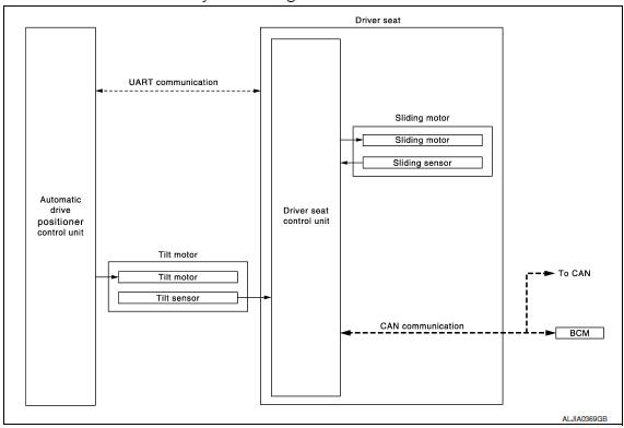
EXIT ASSIST FUNCTION : System Description
OUTLINE
When exiting, if the conditions are satisfied, the seat is moved backward from normal sitting position and the steering column is moved up.
The seat slide amount at entry/exit operation can be changed.
NOTE:
- This function is set to ON before delivery (initial setting).
- - Further information for the system setting procedure. Refer to Owner's Manual.
OPERATION PROCEDURE
- Open the front door LH with ignition switch in OFF position.
- Front seat LH and steering column will move to the exiting position.
OPERATION CONDITION
Satisfy all of the following items. The exit assist function is not performed if these items are not satisfied.
| Item | Request status |
| Ignition switch | OFF |
| System setting [Entry/exit assist function] | ON |
| Initialization | Done |
|
Switch inputs
|
OFF (Not operated) |
| CVT selector lever | P position |
DETAIL FLOW
| Order | Input | Output | Control unit condition |
| 1 | Front door switch LH | - | Driver seat control unit receives front door switch LH signal (open) from BCM via CAN communication |
| 2 | - | Motors (seat sliding, tilt) | Driver seat control unit operates the seat sliding motor, which
recognizes that the driver side door is opened with ignition switch
OFF.
Driver seat control unit then requests the operations of tilt motor to auto drive positioner control unit via UART communication. The automatic drive positioner control unit operates each motor for a constant amount. |
EXIT ASSIST FUNCTION : Component Parts Loca
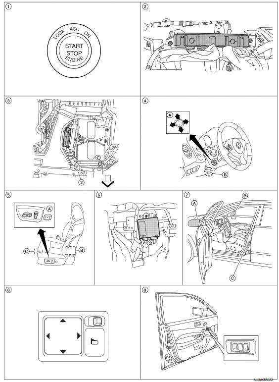
- Push-button ignition switch M38
- BCM M16, M17, M18, M19 (view with instrument panel removed)
- TCM F15
- A. ADP steering switch M39
B. Tilt motor M71, telescopic motor M73 - A. Power seat switch LH B213
B. Reclining motor B222
C. Driver seat control unit B203, B211 - Automatic drive positioner control unit M63, M67 (view with instrument panel removed)
- A. Door mirror LH D4
B. Door mirror RH D107
C. Front door switch LH B8 - Door mirror remote control switch M108
- Seat memory switch D13
 : Front
EXIT ASSIST FUNCTION : Component Description
CONTROL UNITS
| Item | Function |
| Driver seat control unit |
|
| Automatic drive positioner control unit | Operates the tilt motor with the request from the driver seat control unit |
| BCM |
Recognizes the following status and transmits it to the driver seat control unit via CAN communication.
|
INPUT PARTS
Switches
| Item | Function |
| Front door switch LH | Detect front door LH open/close statu |
Sensors
| Item | Function |
| Tilt sensor | Detect the up/down position of steering column. |
| Sliding sensor | Detect the front/rear position of seat. |
OUTPUT PARTS
| Item | Function |
| Tilt motor | Move the steering column up/down. |
| Sliding motor | Slide the seat forward/backward |
 Memory function
MEMORY FUNCTION : System
MEMORY FUNCTION : System Description
OUTLINE
The driver seat control unit can store the optimum driving positions (seat,
steering column and door mirror position) for ...
 Entry assist function
ENTRY ASSIST FUNCTION : System Diagram
ENTRY ASSIST FUNCTION : System Description
OUTLINE
The seat is in the exiting position when either following condition is
satisfied, the seat returns fr ...
Other materials:
U1000 CAN comm circuit
Description
CAN (Controller Area Network) is a serial communication line for real time
application. It is an on-vehicle multiplex
communication line with high data communication speed and excellent malfunction
detection ability.
Many electronic control units are equipped onto a vehicle, an ...
Explanation of scheduled maintenance items
The following descriptions are provided to give
you a better understanding of the scheduled
maintenance items that should be regularly
checked or replaced. The maintenance schedule
indicates at which mileage/time intervals each
item requires service.
In addition to scheduled maintenance, you ...
Key slot
Removal and Installation
REMOVAL
Remove the instrument lower panel LH. Refer to
IP-19, "Removal and Installation".
Remove the switch assembly screws (A), remove
the key slot
screws (B) and then remove key slot (1) from instrument lower
panel LH (2).
IN ...
Nissan Maxima Owners Manual
- Illustrated table of contents
- Safety-Seats, seat belts and supplemental restraint system
- Instruments and controls
- Pre-driving checks and adjustments
- Monitor, climate, audio, phone and voice recognition systems
- Starting and driving
- In case of emergency
- Appearance and care
- Do-it-yourself
- Maintenance and schedules
- Technical and consumer information
Nissan Maxima Service and Repair Manual

0.0062