Nissan Maxima Service and Repair Manual: Memory function
MEMORY FUNCTION : System
MEMORY FUNCTION : System Description
OUTLINE
The driver seat control unit can store the optimum driving positions (seat,
steering column and door mirror position) for 2 people. If the front seat
position is changed, one-touch (pressing desired memory switch) operation
allows changing to the other driving position.
NOTE:
Further information for the memory storage procedure. Refer to Owner's Manual.
OPERATION PROCEDURE
- Turn ignition switch ON
- Press desired memory switch.
- Front seat LH, steering column and door mirror will move to the memorized position.
OPERATION CONDITION
Satisfy all of the following items. The memory function is not performed if these items are not satisfied.
| Item | Request status |
| Ignition position | ON |
|
Switch inputs
|
OFF (Not operated) |
| CVT selector lever | P position |
However, the memory operation can be performed for 45 seconds after opening the front door LH (front door switch LH OFF → ON) even if the ignition switch is OFF.
DETAIL FLOW
| Order | Input | Output | Control unit condition |
| 1 | Memory switch | - | The memory switch signal is inputted to the
automatic drive positioner control unit when memory switch 1 or 2 is
operated.
Memory switch signal is input to driver seat control unit via UART communication |
| 2 | - | Motors (seat, steering, door mirror) | Driver seat control unit operates each motor of seat when it recognizes the memory switch pressed and requests each motor operation to automatic drive positioner control unit via UART communication. The automatic drive positioner control unit operates each motor. |
| Memory switch Indicator | Driver seat control unit requests the flashing of memory indicator to automatic drive positioner control unit via UART communication while either of the motors is operating. The automatic drive positioner control unit illuminates the memory indicator. | ||
| 3 | Sensors (seat, steering column, door mirrors) | - | Driver seat control unit judges the operating seat position with each seat sensor input. The positions of the steering column and outside mirrors are monitored with each sensor signal that is input from auto drive positioner control unit via UART communication. Driver seat control unit stops the operation of each motor when each part reaches the recorded address |
| 4 | - | Memory switch Indicator | Driver seat control unit requests the illumination of memory indicator to auto drive positioner control unit via UART communication after all motors stop. The auto driving positioner control unit illuminates the memory indicator for 5 seconds |
MEMORY FUNCTION : Component Parts Location
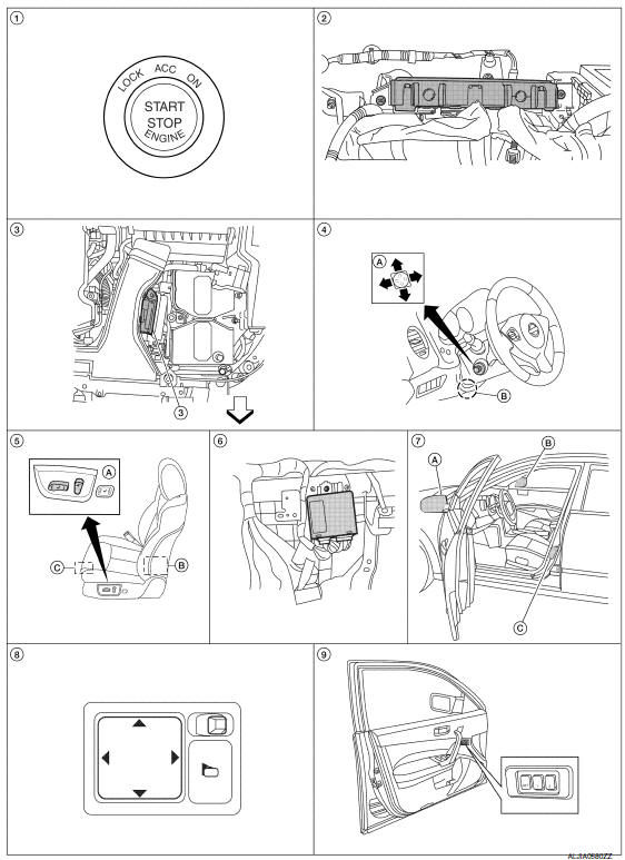
- Push-button ignition switch M38
- BCM M16, M17, M18, M19 (view with instrument panel removed)
- TCM F15
- A. ADP steering switch M39
B. Tilt motor M71, telescopic motor M73 - A. Power seat switch LH B213
B. Reclining motor B222
C. Driver seat control unit B203, B211 - Automatic drive positioner control unit M63, M67 (view with instrument panel removed)
- A. Door mirror LH D4
B. Door mirror RH D107
C. Front door switch LH B8 - Door mirror remote control switch M108
- Seat memory switch D13
: Front
MEMORY FUNCTION : Component Description
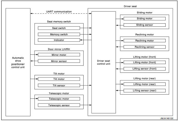
CONTROL UNITS
| Item | Function |
| Driver seat control unit |
|
| Automatic drive positioner control unit | Operates the steering column and door mirrors with the instructions from the driver seat control unit. |
INPUT PARTS
Switches
| Item | Function |
| Memory switch 1/2 | The registration and memory function can be performed with its operation. |
Sensors
| Item | Function |
| Door mirror sensor (LH/RH) | Detect the up/down and left/right position of outside mirror face. |
| Tilt and telescopic sensors | Detect the up/down and front/rear position of steering column |
| Lifting sensor (front) | Detect the up/down position of seat lifting (front). |
| Lifting sensor (rear) | Detect the up/down position of seat lifting (rear). |
| Reclining sensor | Detect the tilt of seatback |
| Sliding sensor | Detect the front/rear position of seat. |
OUTPUT PARTS
| Item | Function |
| Door mirror motor (LH/RH) | Move the outside mirror face upward/downward and leftward/rightw |
| Tilt and telescopic motors | Move the steering column up/down and front/rear. |
| Lifting motor (front) | Move the seat lifter (front) upward/downward |
| Lifting motor (rear) | Move the seat lifter (rear) upward/downward |
| Reclining motor | Tilt and raise up the s |
| Sliding motor | Slide the seat forward/backward |
| Memory indicat | Illuminates or blinks according to the registration/operation status. |
 Manual function
MANUAL FUNCTION : System Diagram
MANUAL FUNCTION : System Descriptio
OUTLINE
The driving position (seat, steering column and door mirror position) can be
adjusted manually with power seat swi ...
 Exit assist function
EXIT ASSIST FUNCTION : System Diagram
EXIT ASSIST FUNCTION : System Description
OUTLINE
When exiting, if the conditions are satisfied, the seat is moved backward
from normal sitting position ...
Other materials:
Audio antenna
Location of Antenna
AV control unit
AV control unit antenna feeder
In-line connectors M103, M501
Antenna amp.
Window antenna
Satellite radio antenna feeder
Satellite radio antenna
Window Antenna Repair
ELEMENT CHECK
Attach probe circuit tester (ohm setting) to antenna ...
Warning signals
To help prevent the vehicle from moving unexpectedly
by erroneous operation of the Intelligent
Key or to help prevent the vehicle from being
stolen, a chime or buzzer sounds from inside and
outside the vehicle and a warning is displayed in
the instrument panel.
When a chime or beep sounds or ...
Parking lamp circuit
Description
The IPDM E/R (intelligent power distribution module engine room) controls the
tail lamp relay based on inputs from the BCM over the CAN communication
lines. When the tail lamp relay is energized, power flows through fuses 46
and 47, located in the IPDM E/R. Power then flows to the ...
Nissan Maxima Owners Manual
- Illustrated table of contents
- Safety-Seats, seat belts and supplemental restraint system
- Instruments and controls
- Pre-driving checks and adjustments
- Monitor, climate, audio, phone and voice recognition systems
- Starting and driving
- In case of emergency
- Appearance and care
- Do-it-yourself
- Maintenance and schedules
- Technical and consumer information
Nissan Maxima Service and Repair Manual

0.0067