Nissan Maxima Service and Repair Manual: BCM branch line circuit
Diagnosis Procedure
1.CHECK CONNECTOR
- Turn the ignition switch OFF.
- Disconnect the battery cable from the negative terminal.
- Check the terminals and connectors of the BCM for damage, bend and loose connection (unit side and connector side).
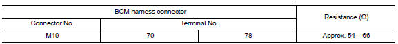
2.CHECK HARNESS FOR OPEN CIRCUIT
- Disconnect the connector of BCM.
- Check the resistance between the BCM harness connector terminals.
3.CHECK POWER SUPPLY AND GROUND CIRCUIT
Check the power supply and the ground circuit of the BCM. Refer to BCS-36, "Diagnosis Procedure".
Is the inspection result normal?
 ADP branch line circuit
Diagnosis Procedure
1.CHECK CONNECTOR
Turn the ignition switch OFF.
Disconnect the battery cable from the negative terminal.
Check the following terminals and connectors for damage, bend and ...
 DLC branch line circuit
Diagnosis Procedure
1.CHECK CONNECTOR
Turn the ignition switch OFF.
Disconnect the battery cable from the negative terminal.
Check the terminals and connectors of the data link connector for ...
Other materials:
Basic inspection
DIAGNOSIS AND REPAIR WORKFLOW
Work Flow
OVERALL SEQUENCE
DETAILED FLOW
1.OBTAIN INFORMATION ABOUT SYMPTOM
Interview the customer to obtain as much information as possible about the
conditions and environment under
which the malfunction occurred.
>> GO TO 2
2.CHECK SYMPTOM
Chec ...
Changing engine oil filter
1. Park the vehicle on a level surface and apply
the parking brake.
2. Turn the engine off.
3. Place a large drain pan under the oil filter B .
4. Remove clips A from the right engine protector
located inside the right wheel well and
then remove protector. Remove oil filter B
with an ...
Combination meter
Reference Value
VALUES ON THE DIAGNOSIS TOOL
NOTE:
* The monitor will indicate "OFF" even though the brake warning
lamp is on if either of the following conditions exist:
The parking brake is engaged
The brake fluid level is low
TERMINAL LAYOUT
PHYSICAL VALUES
Fail Safe
...
Nissan Maxima Owners Manual
- Illustrated table of contents
- Safety-Seats, seat belts and supplemental restraint system
- Instruments and controls
- Pre-driving checks and adjustments
- Monitor, climate, audio, phone and voice recognition systems
- Starting and driving
- In case of emergency
- Appearance and care
- Do-it-yourself
- Maintenance and schedules
- Technical and consumer information
Nissan Maxima Service and Repair Manual

0.0071