Nissan Maxima Service and Repair Manual: DLC branch line circuit
Diagnosis Procedure
1.CHECK CONNECTOR
- Turn the ignition switch OFF.
- Disconnect the battery cable from the negative terminal.
- Check the terminals and connectors of the data link connector for damage, bend and loose connection (connector side and harness side).
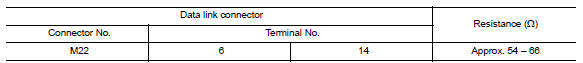
2.CHECK HARNESS FOR OPEN CIRCUIT
Check the resistance between the data link connector terminals.
 BCM branch line circuit
Diagnosis Procedure
1.CHECK CONNECTOR
Turn the ignition switch OFF.
Disconnect the battery cable from the negative terminal.
Check the terminals and connectors of the BCM for damage, bend and ...
 M&A branch line circuit
Diagnosis Procedure
1.CHECK CONNECTOR
Turn the ignition switch OFF.
Disconnect the battery cable from the negative terminal.
Check the terminals and connectors of the combination meter for
...
Other materials:
P0605 ECM
Description
The ECM consists of a microcomputer and connectors for signal
input and output and for power supply. The ECM controls the engine
DTC Logic
DTC DETECTION LOGIC
DTC CONFIRMATION PROCEDURE
1.PRECONDITIONING
If DTC Confirmation Procedure has been previously conducted, always ...
Hazard switch
Component Function Check
1.CHECK HAZARD SWITCH SIGNAL BY CONSULT
CONSULT DATA MONITOR
Turn ignition switch ON.
Select "HAZARD SW" of BCM (FLASHER) DATA MONITOR item.
With operating the hazard switch, check the monitor status.
Diagnosis Procedure
1.CHECK HAZARD SWITCH SIGNAL INPUT
...
Maintenance under severe operating conditions
Severe driving conditions
The maintenance intervals shown on the preceding pages are for normal
operating conditions. If the vehicle is mainly operated under severe driving
conditions as shown below, more frequent maintenance must be performed on the
following items as shown in the table.
...
Nissan Maxima Owners Manual
- Illustrated table of contents
- Safety-Seats, seat belts and supplemental restraint system
- Instruments and controls
- Pre-driving checks and adjustments
- Monitor, climate, audio, phone and voice recognition systems
- Starting and driving
- In case of emergency
- Appearance and care
- Do-it-yourself
- Maintenance and schedules
- Technical and consumer information
Nissan Maxima Service and Repair Manual

0.006