Nissan Maxima Service and Repair Manual: ADP branch line circuit
Diagnosis Procedure
1.CHECK CONNECTOR
-
Turn the ignition switch OFF.
-
Disconnect the battery cable from the negative terminal.
-
Check the following terminals and connectors for damage, bend and loose connection (unit side and connector side).
-
Driver seat control unit
-
Harness connector B208
-
Harness connector B32
-
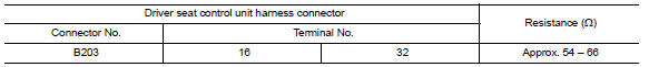
2.CHECK HARNESS FOR OPEN CIRCUIT
-
Disconnect the connector of driver seat control unit.
-
Check the resistance between the driver seat control unit harness connector terminals.
3.CHECK POWER SUPPLY AND GROUND CIRCUIT
Check the power supply and the ground circuit of the driver seat control unit. Refer to ADP-47, "DRIVER SEAT CONTROL UNIT : Diagnosis Procedure".
 ECM branch line circuit
Diagnosis Procedure
1.CHECK CONNECTOR
Turn the ignition switch OFF.
Disconnect the battery cable from the negative
terminal.
Check the following terminals ...
 BCM branch line circuit
Diagnosis Procedure
1.CHECK CONNECTOR
Turn the ignition switch OFF.
Disconnect the battery cable from the negative
terminal.
Check the terminals and connec ...
Other materials:
Headlamp (HI) circuit
Description
The IPDM E/R (intelligent power distribution module engine room) controls the
headlamp high relay based on inputs from the BCM over the CAN communication
lines. When the headlamp high relay is energized, power flows through fuses
48 and 49, located in the IPDM E/R. Power then flow ...
Timing Chain
Exploded View
Timing chain tensioner (secondary)
Internal chain guide
Timing chain tensioner (secondary)
Camshaft sprocket (EXH)
Timing chain (secondary)
Timing chain (primary)
Camshaft sprocket (INT)
Camshaft sprocket (INT)
Timing chain (secondary)
Camshaft sprocket (E ...
Power steering fluid
Check the fluid level in the reservoir.
The fluid level should be checked when the fluid
is cold at fluid temperatures of 32 to 86ºF (0 to
30ºC). The fluid level can be checked with the
level gauge which is attached to the cap. To
check the fluid level, remove the cap. The fluid ...
Nissan Maxima Owners Manual
- Illustrated table of contents
- Safety-Seats, seat belts and supplemental restraint system
- Instruments and controls
- Pre-driving checks and adjustments
- Monitor, climate, audio, phone and voice recognition systems
- Starting and driving
- In case of emergency
- Appearance and care
- Do-it-yourself
- Maintenance and schedules
- Technical and consumer information
Nissan Maxima Service and Repair Manual

0.0055