Nissan Maxima Service and Repair Manual: BCM branch line circuit
Diagnosis Procedure
1.CHECK CONNECTOR
-
Turn the ignition switch OFF.
-
Disconnect the battery cable from the negative terminal.
-
Check the terminals and connectors of the BCM for damage, bend and loose connection (unit side and connector side).
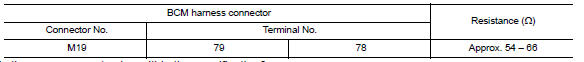
2.CHECK HARNESS FOR OPEN CIRCUIT
-
Disconnect the connector of BCM.
-
Check the resistance between the BCM harness connector terminals.
3.CHECK POWER SUPPLY AND GROUND CIRCUIT
Check the power supply and the ground circuit of the BCM. Refer to BCS-36, "Diagnosis Procedure".
 ADP branch line circuit
Diagnosis Procedure
1.CHECK CONNECTOR
Turn the ignition switch OFF.
Disconnect the battery cable from the negative
terminal.
Check the following terminals ...
 DLC branch line circuit
Diagnosis Procedure
1.CHECK CONNECTOR
Turn the ignition switch OFF.
Disconnect the battery cable from the negative
terminal.
Check the terminals and connec ...
Other materials:
P0725 engine speed
Description
The engine speed signal is transmitted from ECM to TCM via CAN communication
line.
DTC Logic
DTC DETECTION LOGIC
DTC CONFIRMATION PROCEDURE
CAUTION:
Always drive vehicle at a safe speed.
NOTE:
Immediately after performing any "DTC CONFIRMATION PROCEDURE", always turn
igni ...
Back-up lamp
Wiring Diagram
...
Daytime running light system
System Diagram
System Description
The headlamp system for Canada vehicles is equipped with a daytime light
relay that activates the high beam headlamps at approximately half
illumination whenever the engine is running. If the parking brake is
depressed before the engine is started, the day ...
Nissan Maxima Owners Manual
- Illustrated table of contents
- Safety-Seats, seat belts and supplemental restraint system
- Instruments and controls
- Pre-driving checks and adjustments
- Monitor, climate, audio, phone and voice recognition systems
- Starting and driving
- In case of emergency
- Appearance and care
- Do-it-yourself
- Maintenance and schedules
- Technical and consumer information
Nissan Maxima Service and Repair Manual

0.0058