Nissan Maxima Service and Repair Manual: Power generation voltage variable control system operation inspection
Diagnosis Procedure
CAUTION: When performing this inspection, always use a charged battery that has completed the battery inspection.
(When the charging rate of the battery is low, the response speed of the voltage change will become slow. This can cause an incorrect inspection.)
1.CHECK ECM (CONSULT)
Perform ECM self-diagnosis with CONSULT.
2.CHECK OPERATION OF POWER GENERATION VOLTAGE VARIABLE CONTROL SYSTEM
- Connect CONSULT and start the engine.
- The selector lever is in "P" or "N" position and all of the electric loads and A/C, etc. are turned OFF.
- Select "ALTERNATOR DUTY" in "Active Test" of "ENGINE", and then check the value of "BATTERY VOLT" monitor when DUTY value of "ALTERNATOR DUTY" is set to 40.0 %.
"BATTERY VOLT" 2 seconds after setting the DUTY value of "ALTERNATOR DUTY" to 40.0 % : 12 - 13.6 V
- Check the value of "BATTERY VOLT" monitor when DUTY value of "ALTERNATOR DUTY" is set to 80.0%.
"BATTERY VOLT" 20 seconds after setting the DUTY value of "ALTERNATOR DUTY" to 80.0 % : +0.5 V or more against the value of "BATTERY VOLT" monitor when DUTY value is 40.0 %
3.CHECK IPDM E/R (CONSULT)
Perform IPDM E/R self-diagnosis with CONSULT
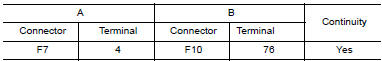
4.CHECK HARNESS BETWEEN GENERATOR AND IPDM E/R
- Turn ignition switch OFF.
- Disconnect generator connector and IPDM E/R connector.
- Check continuity between generator harness connector F7 (A) terminal 4 and IPDM E/R harness connector F10 (B) terminal 76.
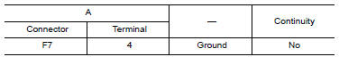
- Check continuity between generator harness connector F7 (A) terminal 4 and ground.
 DTC/circuit diagnosis
CHARGING SYSTEM PRELIMINARY INSPECTION
Diagnosis Procedure
1.CHECK BATTERY TERMINALS CONNECTION
Check if battery terminals are clean and tight
2.CHECK FUSE
Check for blown fuse and fusible link.
...
 B terminal circuit
Description
"B" terminal circuit supplies power to charge the battery and operate the
vehicle's electrical system.
Diagnosis Procedure
1.CHECK "B" TERMINAL CONNECTION
Turn ignition switch OFF ...
Other materials:
Wiring diagram
COLOR DISPLAY
Wiring Diagram - With BOSE audio system With Navigation System
...
ABS branch line circuit
Diagnosis Procedure
1.CHECK CONNECTOR
Turn the ignition switch OFF.
Disconnect the battery cable from the negative terminal.
Check the terminals and connectors of the ABS actuator and
electric unit (control unit) for damage, bend
and loose connection (unit side and connector side).
...
Audio System
For additional information, refer to the separate
Navigation Owner's Manual.
Antenna
The antenna pattern is printed inside the rear
window.
CAUTION
Do not place metalized film near the
rear window glass or attach any metal
parts to it. This may cause poor reception
or noise.
When cl ...
Nissan Maxima Owners Manual
- Illustrated table of contents
- Safety-Seats, seat belts and supplemental restraint system
- Instruments and controls
- Pre-driving checks and adjustments
- Monitor, climate, audio, phone and voice recognition systems
- Starting and driving
- In case of emergency
- Appearance and care
- Do-it-yourself
- Maintenance and schedules
- Technical and consumer information
Nissan Maxima Service and Repair Manual

0.0198