Nissan Maxima Service and Repair Manual: L terminal circuit (open)
Description
The "L" terminal circuit controls the charge warning lamp. The charge warning lamp turns ON when the ignition switch is set to ON or START. When the generator is providing sufficient voltage with the engine running, the charge warning lamp turns OFF. If the charge warning lamp illuminates with the engine running, a malfunction is indicated.
Diagnosis Procedure
1.CHECK "L" TERMINAL CONNECTION
- Turn ignition switch OFF.
- Check if "L" terminal is clean and tight.
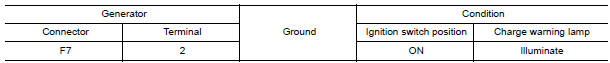
2.CHECK "L" TERMINAL CIRCUIT (OPEN)
- Disconnect the generator connector.
- Apply ground to generator harness connector terminal.
- Check condition of the charge warning lamp with the ignition switch in the ON position.
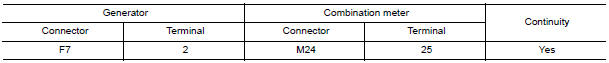
3.CHECK HARNESS CONTINUITY (OPEN CIRCUIT)
- Disconnect the battery cable from the negative terminal.
- Disconnect the combination meter connector.
- Check continuity between generator harness connector and combination meter harness connector.
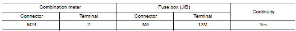
4.CHECK HARNESS CONTINUITY (OPEN CIRCUIT)
Check continuity between combination meter harness connector and fuse block (J/B).
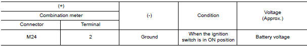
5.CHECK POWER SUPPLY CIRCUIT
- Connect the battery cable to the negative terminal.
- Check voltage between combination meter harness connector and ground.
 B terminal circuit
Description
"B" terminal circuit supplies power to charge the battery and operate the
vehicle's electrical system.
Diagnosis Procedure
1.CHECK "B" TERMINAL CONNECTION
Turn ignition switch OFF ...
 L terminal circuit (short)
Description
The terminal "L" circuit controls the charge warning lamp. The charge warning
lamp turns ON when the ignition
switch is set to ON or START. When the generator is providing sufficient ...
Other materials:
Front fog lamp
Exploded View
Front bumper fascia
Front fog lamp
Front fog lamp bracket
Clip
Spring nuts
Removal and Installation
FRONT FOG LAMP
Removal
Remove the front bumper fascia. Refer to EXT-16, "Removal and
Installation".
Disconnect the harness connector from the fog lam ...
Subwoofer
Description
The AV control unit sends audio signals to the BOSE speaker amp. The BOSE
speaker amp. amplifies the
audio signals before sending them to the subwoofers using the audio signal
circuits.
Diagnosis Procedure
1.CONNECTOR CHECK
Check the AV control unit, BOSE speaker amp. and subwo ...
Satellite radio tuner
Removal and Installation
REMOVAL
Disconnect the battery negative terminal.
Remove the trunk upper finisher. Refer to INT-36, "Exploded View".
Remove the parcel shelf finisher. Refer to INT-28, "Removal and
Installation".
From inside the passenger compartment, remove the bracket screw ...
Nissan Maxima Owners Manual
- Illustrated table of contents
- Safety-Seats, seat belts and supplemental restraint system
- Instruments and controls
- Pre-driving checks and adjustments
- Monitor, climate, audio, phone and voice recognition systems
- Starting and driving
- In case of emergency
- Appearance and care
- Do-it-yourself
- Maintenance and schedules
- Technical and consumer information
Nissan Maxima Service and Repair Manual

0.0062