Nissan Maxima Owners Manual: FEB system operation
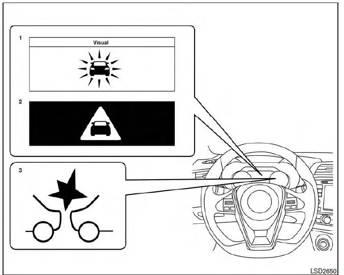
1. Vehicle ahead detection indicator
2. FEB warning indicator
3. FEB system warning light
The FEB system will function when your vehicle is driven at speeds above approximately 3 mph (5 km/h).
If a risk of a forward collision is detected, the FEB system will provide an initial warning to the driver by both a visual and audible alert.
If the driver applies the brakes quickly and forcefully after the warning, and the FEB system detects that there is still the possibility of a forward collision, the system will automatically increase the braking force. If the driver does not take action, the FEB system issues the second visual warning (red) and audible warning and also applies partial braking.
If the risk of a collision becomes imminent, the FEB system applies harder braking automatically.
NOTE:
The vehicle's brake lights come on when braking is performed by the forward emergency braking system.
Depending on vehicle speed and distance to the vehicle ahead, as well as driving and roadway conditions, the system may help the driver avoid a forward collision or may help mitigate the consequences of a collision, should one be unavoidable.
If the driver is handling the steering wheel, accelerating or braking, the FEB system will function later or will not function.
The automatic braking will cease under the following conditions:
- When the steering wheel is turned as far as necessary to avoid a collision.
- When the accelerator pedal is depressed.
- When there is no longer a vehicle detected ahead.
If the FEB system has stopped the vehicle, the vehicle will remain at a standstill for approximately 2 seconds before the brakes are released.
 Forward Emergency Braking (FEB) (if so equipped)
WARNING
Failure to follow the warnings and instructions
for proper use of the FEB system
could result in serious injury or death.
The FEB system is a supplemental aid
to the driver. It is not ...
 Turning the FEB system on/off
Perform the following steps to turn the FEB systems
ON or OFF.
1. Press the button until
"Settings" displays
in the vehicle information display and
then press OK button. Use the ...
Other materials:
Glove box
Open the glove box by pulling the handle. Use the
master key when locking or unlocking the glove
box.
There is a trunk cancel switch in the glove box.
For additional information, refer to "Cancel
switch" in the "Pre-driving checks and adjustments"
section of this manual.
WARNING
Keep g ...
Normal operating condition
Description
The majority of the audio concerns are the result of outside causes (bad CD,
electromagnetic interference, etc.).
NOISE
The following noise results from variations in field strength, such as fading
noise and multi-path noise, or external noise from trains and other sources.
It i ...
P0607 ECM
Description
CAN (Controller Area Network) is a serial communication line for real time
application. It is an on-vehicle multiplex
communication line with high data communication speed and excellent error
detection ability. Many electronic
control units are equipped onto a vehicle, and each ...
Nissan Maxima Owners Manual
- Illustrated table of contents
- Safety-Seats, seat belts and supplemental restraint system
- Instruments and controls
- Pre-driving checks and adjustments
- Monitor, climate, audio, phone and voice recognition systems
- Starting and driving
- In case of emergency
- Appearance and care
- Do-it-yourself
- Maintenance and schedules
- Technical and consumer information
Nissan Maxima Service and Repair Manual

0.0074