Nissan Maxima Service and Repair Manual: Center speaker
Description
The AV control unit sends audio signals to the BOSE speaker amp. The BOSE speaker amp. amplifies the audio signals before sending them to the center speaker using the audio signal circuits.
Diagnosis Procedure
1.CONNECTOR CHECK
Check the AV control unit, BOSE speaker amp. and speaker connectors for the following:
- Proper connection
- Damage
- Disconnected or loose terminals
2.HARNESS CHECK
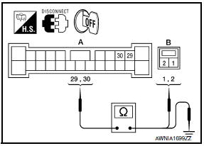
- Disconnect BOSE speaker amp. connector B109 and center speaker connector M130.
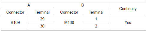
- Check continuity between BOSE speaker amp. harness connector B109 (A) and center speaker harness connector M130 (B).
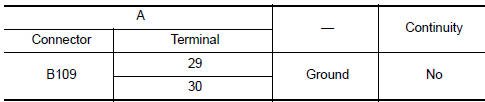
- Check continuity between BOSE speaker amp. harness connector B109 (A) and ground.
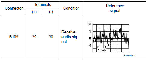
3.CENTER SPEAKER SIGNAL CHECK
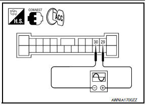
- Connect BOSE speaker amp. connector B109 and center speaker connector.
- Turn ignition switch to ACC.
- Push POWER switch.
- Check the signal between BOSE speaker amp. harness connector B109 terminals with CONSULT or oscilloscope.
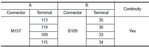
4.HARNESS CHECK
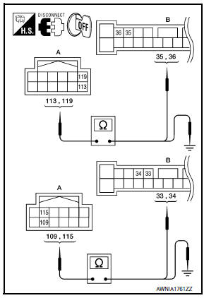
- Disconnect AV control unit connector M157 and BOSE speaker amp. connector B109.
- Check continuity between AV control unit harness connector M157 (A) and BOSE speaker amp. harness connector B109 (B).
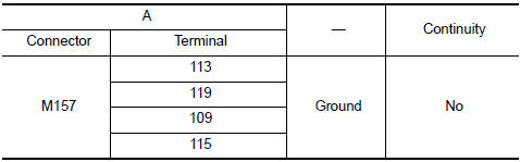
- Check continuity between AV control unit harness connector M157 (A) and ground.
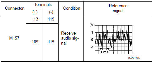
5.CENTER SPEAKER SIGNAL CHECK
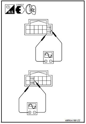
- Connect AV control unit connector and BOSE speaker amp.
connector.
- Turn ignition switch to ACC.
- Push POWER switch.
- Check the signal between AV control unit harness connector terminals with CONSULT or oscilloscope.
 Tweeter
Description
The AV control unit sends audio signals to the BOSE speaker amp. The BOSE
speaker amp. amplifies the
audio signals before sending them to the tweeters using the audio signal
circuit ...
 Rear door speaker
Description
The AV control unit sends audio signals to the BOSE speaker amp. The BOSE
speaker amp. amplifies the
audio signals before sending them to the rear door speakers using the audio
sign ...
Other materials:
P0335 CKP sensor (POS)
Description
The crankshaft position sensor (POS) is located on the oil pan facing
the gear teeth (cogs) of the signal plate. It detects the fluctuation of
the engine revolution.
The sensor consists of a permanent magnet and Hall IC.
When the engine is running, the high and low parts o ...
C1155 BR fluid level low
Description
The brake fluid level switch converts the brake fluid level to an electric
signal and transmits it to the ABS actuator
and electric unit (control unit).
DTC Logic
DTC DETECTION LOGIC
DTC CONFIRMATION PROCEDURE
1.CHECK SELF-DIAGNOSIS RESULTS
Check the self-diagnosis results. ...
Diagnosis and repair work flow
Work Flow
INTRODUCTION
The TCM receives signals from the vehicle speed sensor and transmission range
switch. Then it provides shift
control or lock-up control via CVT solenoid valves.
The TCM also communicates with the ECM by means of signals
sent from sensing elements used with the OBD-r ...
Nissan Maxima Owners Manual
- Illustrated table of contents
- Safety-Seats, seat belts and supplemental restraint system
- Instruments and controls
- Pre-driving checks and adjustments
- Monitor, climate, audio, phone and voice recognition systems
- Starting and driving
- In case of emergency
- Appearance and care
- Do-it-yourself
- Maintenance and schedules
- Technical and consumer information
Nissan Maxima Service and Repair Manual

0.0066