Nissan Maxima Service and Repair Manual: C1155 BR fluid level low
Description
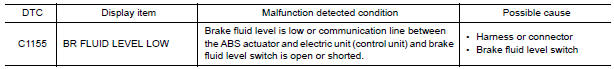
The brake fluid level switch converts the brake fluid level to an electric signal and transmits it to the ABS actuator and electric unit (control unit).
DTC Logic
DTC DETECTION LOGIC
DTC CONFIRMATION PROCEDURE
1.CHECK SELF-DIAGNOSIS RESULTS
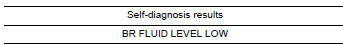
Check the self-diagnosis results.
Diagnosis Procedure
CAUTION: Check brake fluid level in brake reservoir tank before starting inspection.
1.CONNECTOR INSPECTION
- Turn ignition switch OFF.
- Disconnect brake fluid level switch connector and combination meter connector.
- Check terminals for deformation, disconnection, looseness, and so on. If any malfunction is found, repair or replace terminals.
- Reconnect connector and perform self-diagnosis
2.CHECK BRAKE FLUID LEVEL SWITCH
Perform the brake fluid level switch component inspection
3.CHECK BRAKE FLUID LEVEL SWITCH HARNESS
- Disconnect combination meter connector.
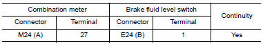
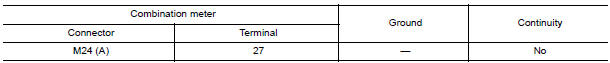
- Check continuity between combination meter connector M24 (A) terminal 27 and brake fluid level switch connector E24 (B) terminal 1.
- Check continuity between combination meter connector M24 (A) terminal 27 and ground.
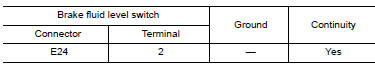
4.CHECK BRAKE FLUID LEVEL SWITCH GROUND CIRCUIT
Check continuity between brake fluid level switch connector E24 terminal 2 and ground.
Component Inspection
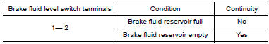
1.CHECK BRAKE FLUID LEVEL SWITCH
- Turn ignition switch OFF.
- Disconnect brake fluid level switch connector.
- . Check continuity between brake fluid level switch terminals 1 and 2.
 C1154 PNP switch
Description
The transmission range switch signal is transmitted to the ABS actuator and
electric unit (control unit) using
the CAN communication lines.
DTC Logic
DTC DETECTION LOGIC
DTC CO ...
 C1156 ST ANG sen com cir
Description
The steering angle sensor is connected to the ABS actuator and electric unit
(control unit) in addition to CAN
lines. CAN (Controller Area Network) is a serial communication line for ...
Other materials:
Vacuum lines
Exploded View
Clamp
Installation arrow
Vacuum hose
Vacuum pipe
Clip
To intake manifold
To brake booster
Front
Removal and Installation
REMOVAL
Disconnect the vacuum hose from the brake booster.
Disconnect the vacuum hose from the intake manifold.
Release the c ...
Vehicle speed signal circuit
Description
Combination meter sends vehicle speed signal to power steering control unit.
Diagnosis Procedure
1.PERFORM COMBINATION METER SELF-DIAGNOSIS
Perform combination meter self-diagnosis.
2.CHECK HARNESS BETWEEN COMBINATION METER AND POWER STEERING CONTROL UNIT FOR
OPEN
Turn the ...
C1115 ABS sensor [abnormal signal]
Description
When the sensor rotor rotates, the magnetic field changes. It converts the
magnetic field changes to current
signals (rectangular wave) and transmits them to the ABS actuator and electric
unit (control unit).
DTC Logic
DTC DETECTION LOGIC
DTC CONFIRMATION PROCEDURE
1.CHECK ...
Nissan Maxima Owners Manual
- Illustrated table of contents
- Safety-Seats, seat belts and supplemental restraint system
- Instruments and controls
- Pre-driving checks and adjustments
- Monitor, climate, audio, phone and voice recognition systems
- Starting and driving
- In case of emergency
- Appearance and care
- Do-it-yourself
- Maintenance and schedules
- Technical and consumer information
Nissan Maxima Service and Repair Manual

0.0067