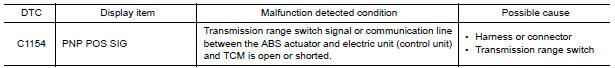
Nissan Maxima Service and Repair Manual: C1154 PNP switch
Description
The transmission range switch signal is transmitted to the ABS actuator and electric unit (control unit) using the CAN communication lines.
DTC Logic
DTC DETECTION LOGIC
DTC CONFIRMATION PROCEDURE
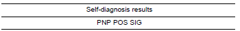
1.CHECK SELF-DIAGNOSIS RESULTS
Check the self-diagnosis results.
Diagnosis Procedure
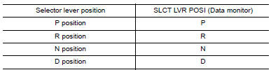
1.CHECK DATA MONITOR
Select "SLCT LVR POSI" in "Data Monitor" and check transmission range switch signal.
2.CHECK TRANSMISSION RANGE SWITCH
Perform transmission range switch inspection.
Special Repair Requirement
1.ADJUSTMENT OF STEERING ANGLE SENSOR NEUTRAL POSITION
Always perform the neutral position adjustment for the steering angle sensor, when replacing the ABS actuator and electric unit (control unit).
 C1147, C1148, C1149, C1150 USV/HSV line
Description
USV1, USV2 (CUT VALVE)
The cut valve shuts off the normal brake fluid path from the master cylinder,
when VDC/TCS is activated.
HSV1, HSV2 (SUCTION VALVE)
The suction valve supplies ...
 C1155 BR fluid level low
Description
The brake fluid level switch converts the brake fluid level to an electric
signal and transmits it to the ABS actuator
and electric unit (control unit).
DTC Logic
DTC DETECTION LOGI ...
Other materials:
Entry assist function
ENTRY ASSIST FUNCTION : System Diagram
ENTRY ASSIST FUNCTION : System Description
OUTLINE
The seat is in the exiting position when either following condition is
satisfied, the seat returns from exiting position to the previous driving
position.
NOTE:
This function is set to OFF befor ...
Water pump
Exploded View
Water pump
O-rings
Timing chain tensioner
Intake valve timing control solenoid
valve cover (RH) (bank 1)
Water pump cover
Removal and Installation
WARNING:
Do not remove the radiator cap when the engine is hot. Serious burns could occur
from high pressure
co ...
Sound signal circuit
SATELLITE RADIO TUNER
SATELLITE RADIO TUNER : Description
Left and right channel audio signals are supplied from the satellite radio
tuner to the AV control unit through the sound signal circuits.
SATELLITE RADIO TUNER : Diagnosis Procedure
LEFT CHANNEL
1.CHECK HARNESS
Turn ignition swi ...
Nissan Maxima Owners Manual
- Illustrated table of contents
- Safety-Seats, seat belts and supplemental restraint system
- Instruments and controls
- Pre-driving checks and adjustments
- Monitor, climate, audio, phone and voice recognition systems
- Starting and driving
- In case of emergency
- Appearance and care
- Do-it-yourself
- Maintenance and schedules
- Technical and consumer information
Nissan Maxima Service and Repair Manual

0.0056