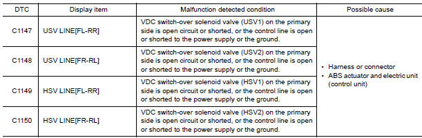
Nissan Maxima Service and Repair Manual: C1147, C1148, C1149, C1150 USV/HSV line
Description
USV1, USV2 (CUT VALVE)
The cut valve shuts off the normal brake fluid path from the master cylinder, when VDC/TCS is activated.
HSV1, HSV2 (SUCTION VALVE)
The suction valve supplies the brake fluid from the master cylinder to the pump, when VDC/TCS is activated.
DTC Logic
DTC DETECTION LOGIC
DTC CONFIRMATION PROCEDURE
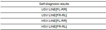
1.CHECK SELF-DIAGNOSIS RESULTS
Check the self-diagnosis results
Diagnosis Procedure
1.CONNECTOR INSPECTION
- Turn ignition switch OFF.
- Disconnect ABS actuator and electric unit (control unit) connector.
- Check terminals for deformation, disconnection, looseness, and so on. If any malfunction is found, repair or replace terminals.
- Reconnect connector and perform self-diagnosis
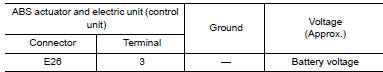
2.CHECK SOLENOID AND ACTUATOR RELAY POWER SUPPLY CIRCUIT
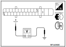
- Turn ignition switch OFF.
- Disconnect ABS actuator and electric unit (control unit) connector.
- Check voltage between ABS actuator and electric unit (control unit) connector E26 terminal 3 and ground.
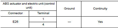
3. CHECK SOLENOID AND ACTUATOR RELAY GROUND CIRCUIT
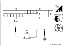
Check continuity between ABS actuator and electric unit (control unit) connector E26 terminals 1, 4 and ground.
Component Inspection
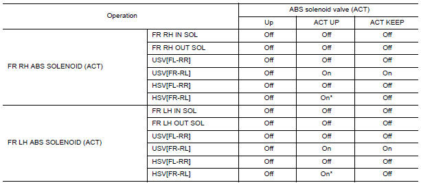
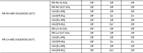
1.CHECK ACTIVE TEST
- Select each test menu item on "ACTIVE TEST".
- On the display, touch "Up", "ACT UP", and "ACT KEEP", and check that the system operates as shown in the table below.
Special Repair Requirement
1.ADJUSTMENT OF STEERING ANGLE SENSOR NEUTRAL POSITION
Always perform the neutral position adjustment for the steering angle sensor, when replacing the ABS actuator and electric unit (control unit).
 C1145, C1146 yaw rate/side/decel G sensor
Description
The yaw rate/side/decel G sensor detects the yaw rate/side/decel G affecting
the vehicle, and transmits the
data to the ABS actuator and electric unit (control unit) as an analog volt ...
 C1154 PNP switch
Description
The transmission range switch signal is transmitted to the ABS actuator and
electric unit (control unit) using
the CAN communication lines.
DTC Logic
DTC DETECTION LOGIC
DTC CO ...
Other materials:
C1109 battery voltage [abnormal]
Description
Supplies electric power to the ABS actuator and electric unit (control unit).
DTC Logic
DTC DETECTION LOGIC
DTC CONFIRMATION PROCEDURE
1.CHECK SELF-DIAGNOSIS RESULTS
Check the self-diagnosis results.
Diagnosis Procedure
1.CONNECTOR INSPECTION
Turn ignition switch OFF. ...
Diagnosis system (driver seat C/U)
Diagnosis Description
The auto drive positioner system can be checked and diagnosed for component
operation with CONSULT.
DIAGNOSTIC MODE
Diagnostic mode [AUTO DRIVE POS.]
Description
WORK SUPPORT
Changes the setting of each function
SELF DIAGNOSTIC RESULT
Perf ...
Front fog lamp system
Wiring Diagram
...
Nissan Maxima Owners Manual
- Illustrated table of contents
- Safety-Seats, seat belts and supplemental restraint system
- Instruments and controls
- Pre-driving checks and adjustments
- Monitor, climate, audio, phone and voice recognition systems
- Starting and driving
- In case of emergency
- Appearance and care
- Do-it-yourself
- Maintenance and schedules
- Technical and consumer information
Nissan Maxima Service and Repair Manual

0.0063