Nissan Maxima Service and Repair Manual: C1145, C1146 yaw rate/side/decel G sensor
Description
The yaw rate/side/decel G sensor detects the yaw rate/side/decel G affecting the vehicle, and transmits the data to the ABS actuator and electric unit (control unit) as an analog voltage signal.
DTC Logic
DTC DETECTION LOGIC
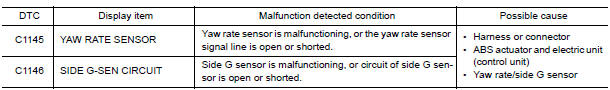
DTC CONFIRMATION PROCEDURE
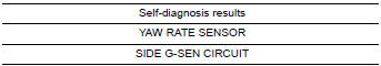
1.CHECK SELF-DIAGNOSIS RESULTS
Check the self-diagnosis results.
Diagnosis Procedure
CAUTION:
- Sudden turns (such as spin turns, acceleration turns), drifting, etc., when VDC function is off (VDC OFF switch "ON") may cause yaw rate/side/decel G sensor system to indicate a malfunction. However, this is not a malfunction if normal operation can be resumed after restarting engine. Then erase memory of self-diagnosis.
- If vehicle is on turn-table at entrance to parking garage, or
on other moving surfaces, SLIP indicator
lamp may illuminate and CONSULT self-diagnosis may indicate yaw rate sensor
system malfunction.
However, in this case there is no malfunction in yaw rate sensor system. Take vehicle off of turntable or other moving surfaces, and start engine. Results will return to normal. Also, after doing spin turns or acceleration turns with VDC function off (VDC OFF switch "ON"), the results will return to a normal condition by re-starting vehicle.
1.CONNECTOR INSPECTION
- Turn ignition switch OFF.
- Disconnect yaw rate/side/decel G sensor connector and ABS actuator and electric unit (control unit) connector.
- Check terminals for deformation, disconnection, looseness, and so on. If any malfunction is found, repair or replace terminals.
- Reconnect connectors and perform self-diagnosis
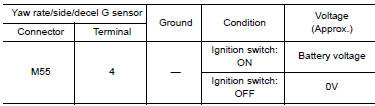
2.CHECK YAW RATE/SIDE/DECEL G SENSOR POWER SUPPLY CIRCUIT
- Turn ignition switch ON, then OFF.
- Check voltage between yaw rate/side/decel G sensor connector M55 terminal 4 and ground.
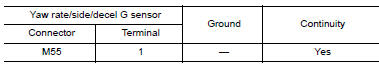
3.CHECK YAW RATE/SIDE/DECEL G SENSOR GROUND CIRCUIT
- Turn ignition switch OFF.
- Check resistance between yaw rate/side/decel G sensor connector M55 terminal 1 and ground.
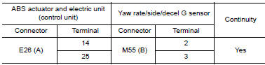
4.CHECK YAW RATE/SIDE/DECEL G SENSOR HARNESS
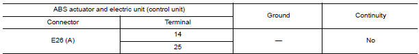
- Check continuity between ABS actuator and electric unit (control unit) connector E26 (A) terminals 14 and 25 and yaw rate/side/ decel G sensor harness connector M55 (B) terminals 2 and 3.
- Check continuity between ABS actuator and electric unit (control unit) connector E26 (A) terminals 14, 25 and ground.
5.CHECK DATA MONITOR
- Connect yaw rate/side/decel G sensor and ABS actuator and electric unit (control unit) connectors.
- Perform the yaw rate/side/decel G sensor component inspection
Component Inspection
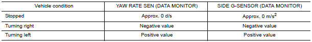
1.CHECK DATA MONITOR
Select "YAW RATE SEN", "SIDE G-SENSOR" in "DATA MONITOR" and check yaw rate/side/decel G sensor signal.
Special Repair Requirement
1.ADJUSTMENT OF STEERING ANGLE SENSOR NEUTRAL POSITION
Always perform the neutral position adjustment for the steering angle sensor, when replacing the ABS actuator and electric unit (control unit).
 C1143, C1144 steering angle sensor
Description
The steering angle sensor detects the rotation amount, angular velocity and
direction of the steering wheel,
and transmits the data to the ABS actuator and electric unit (control unit ...
 C1147, C1148, C1149, C1150 USV/HSV line
Description
USV1, USV2 (CUT VALVE)
The cut valve shuts off the normal brake fluid path from the master cylinder,
when VDC/TCS is activated.
HSV1, HSV2 (SUCTION VALVE)
The suction valve supplies ...
Other materials:
Vehicle identification number (VIN) plate
The vehicle identification number (VIN) plate is
attached as shown. This number is the identification
for your vehicle and is used in the vehicle
registration.
Vehicle identification number (chassis number)
The vehicle identification number is located as
shown.
Engine serial number
...
P0442 evap control system
DTC Logic
DTC DETECTION LOGIC
This diagnosis detects leakage in the EVAP purge line using engine intake
manifold vacuum.
If pressure does not increase, the ECM will check for leakage in the line
between the fuel tank and EVAP canister
purge volume control solenoid valve, under the followi ...
Fuel-filler cap
WARNING
Gasoline is extremely flammable and
highly explosive under certain conditions.
You could be burned or seriously
injured if it is misused or mishandled.
Always stop the engine and do not
smoke or allow open flames or sparks
near the vehicle when refueling.
Do not attempt ...
Nissan Maxima Owners Manual
- Illustrated table of contents
- Safety-Seats, seat belts and supplemental restraint system
- Instruments and controls
- Pre-driving checks and adjustments
- Monitor, climate, audio, phone and voice recognition systems
- Starting and driving
- In case of emergency
- Appearance and care
- Do-it-yourself
- Maintenance and schedules
- Technical and consumer information
Nissan Maxima Service and Repair Manual

0.0063