Nissan Maxima Service and Repair Manual: C1143, C1144 steering angle sensor
Description
The steering angle sensor detects the rotation amount, angular velocity and direction of the steering wheel, and transmits the data to the ABS actuator and electric unit (control unit) via CAN communication.
DTC Logic
DTC DETECTION LOGIC
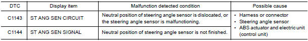
DTC CONFIRMATION PROCEDURE
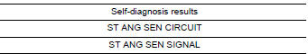
1.CHECK SELF-DIAGNOSIS RESULTS
Check the self-diagnosis results.
Diagnosis Procedure
1.CONNECTOR INSPECTION
- Turn ignition switch OFF.
- Disconnect ABS actuator and electric unit (control unit) connector.
- Check terminals for deformation, disconnection, looseness, and so on. If any malfunction is found, repair or replace terminals.
- Reconnect connector and perform self-diagnosis
2.CHECK STEERING ANGLE SENSOR HARNESS
- Check CAN communication system. Refer to LAN-15, "Trouble Diagnosis Flow Chart".
- Turn ignition switch OFF.
- Disconnect steering angle sensor connector.
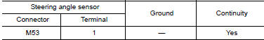
- Check continuity between steering angle sensor harness connector M53 terminal 1 and ground
- Turn ignition switch ON.
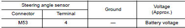
- Check voltage between steering angle sensor connector M53 terminal 4 and ground.
3.CHECK DATA MONITOR
- Turn ignition switch OFF.
- Connect steering angle sensor connector and ABS actuator and electric unit (control unit) connector.
- Perform the steering angle sensor component inspection.
Component Inspection
1.CHECK DATA MONITOR
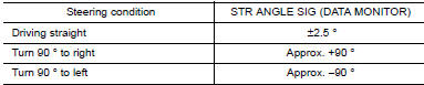
Select "STR ANGLE SIG" in "DATA MONITOR" and check steering angle sensor signal.
Special Repair Requirement
1.ADJUSTMENT OF STEERING ANGLE SENSOR NEUTRAL POSITION
Always perform the neutral position adjustment for the steering angle sensor, when replacing the ABS actuator and electric unit (control unit).
 C1142 press sen circuit
Description
The pressure sensor converts the brake fluid pressure to an electric signal
and transmits it to the ABS actuator
and electric unit (control unit). (The pressure sensor is integrated i ...
 C1145, C1146 yaw rate/side/decel G sensor
Description
The yaw rate/side/decel G sensor detects the yaw rate/side/decel G affecting
the vehicle, and transmits the
data to the ABS actuator and electric unit (control unit) as an analog volt ...
Other materials:
Front fog lamp circuit
Description
The IPDM E/R (intelligent power distribution module engine room) controls the
front fog lamp relay based on inputs from the BCM over the CAN communication
lines. When the front fog lamp relay is energized, power flows from the front
fog lamp relay in the IPDM E/R to the front fog ...
Warning lamp
Description
Warning lamp is built in combination meter.
Intelligent Key system malfunction is reported
to the driver by the warning lamp illumination.
Component Function Check
1.CHECK FUNCTION
Perform "INDICATOR" in the "Active Test" mode
with CON ...
B2630, B2631 sunload sensor
Description
COMPONENT DESCRIPTION
Sunload Sensor
The sunload sensor (1) is located on the driver'side defroster
grille.
It detects sunload entering through windshield by means of a
photo diode. The sensor converts the sunload into a current value,
which is then input into the A/C auto ...
Nissan Maxima Owners Manual
- Illustrated table of contents
- Safety-Seats, seat belts and supplemental restraint system
- Instruments and controls
- Pre-driving checks and adjustments
- Monitor, climate, audio, phone and voice recognition systems
- Starting and driving
- In case of emergency
- Appearance and care
- Do-it-yourself
- Maintenance and schedules
- Technical and consumer information
Nissan Maxima Service and Repair Manual

0.0075