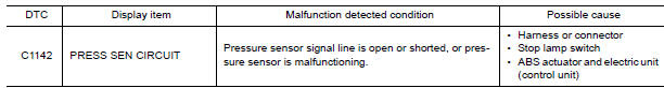
Nissan Maxima Service and Repair Manual: C1142 press sen circuit
Description
The pressure sensor converts the brake fluid pressure to an electric signal and transmits it to the ABS actuator and electric unit (control unit). (The pressure sensor is integrated in the ABS actuator and electric unit (control unit).)
DTC Logic
DTC DETECTION LOGIC
DTC CONFIRMATION PROCEDURE
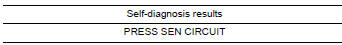
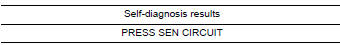
1.CHECK SELF-DIAGNOSIS RESULTS
Check the self-diagnosis results.
Diagnosis Procedure
1.CONNECTOR INSPECTION
- Turn ignition switch OFF.
- Disconnect ABS actuator and electric unit (control unit) connector and stop lamp switch connector.
- Check terminals for deformation, disconnection, looseness and damage. If any malfunction is found, repair or replace terminals.
- Reconnect connectors securely.
- Start engine.
- Pump brake pedal carefully several times, and perform self-diagnosis.
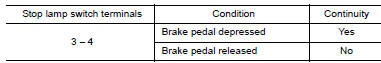
2.CHECK STOP LAMP SWITCH
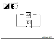
- Turn ignition switch OFF.
- Disconnect stop lamp switch connector.
- Check continuity between stop lamp switch terminals 3 and 4.
3.CHECK STOP LAMP SWITCH CIRCUIT
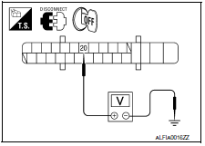
- Disconnect ABS actuator and electric unit (control unit) connector.
- Connect stop lamp switch connector.
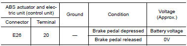
- Check voltage between ABS actuator and electric unit (control unit) connector E26 terminal 20 and ground.
4.CHECK SELF-DIAGNOSIS RESULTS
Check self-diagnosis results.
Component Inspection
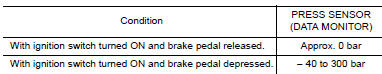
1.CHECK DATA MONITOR
On "DATA MONITOR", select "PRESS SENSOR" and check the brake fluid pressure.
Special Repair Requirement
1.ADJUSTMENT OF STEERING ANGLE SENSOR NEUTRAL POSITION
Always perform the neutral position adjustment for the steering angle sensor, when replacing the ABS actuator and electric unit (control unit).
 C1130, C1131, C1132, C1133, C1136 engine signal
Description
ABS actuator and electric unit (control unit) and ECM exchange the engine
signal with CAN communication
line.
DTC Logic
DTC DETECTION LOGIC
DTC CONFIRMATION PROCEDURE
1.CHECK ...
 C1143, C1144 steering angle sensor
Description
The steering angle sensor detects the rotation amount, angular velocity and
direction of the steering wheel,
and transmits the data to the ABS actuator and electric unit (control unit ...
Other materials:
ECM branch line circuit
Diagnosis Procedure
1.CHECK CONNECTOR
Turn the ignition switch OFF.
Disconnect the battery cable from the negative terminal.
Check the following terminals and connectors for damage, bend and
loose connection (unit side and connector
side).
- Models without automatic drive positione ...
Diagnosis system (HVAC)
CONSULT Function
CONSULT can display each diagnosis item using the diagnosis test modes as
shown.
CONSULT application items
SELF DIAGNOSTIC RESULT
Display Item List
*: Perform self-diagnosis under sunshine. When performing indoors, aim a
light (more than 60 W) at sunload sensor, ...
Drive belt
VQ35DE engine
1. Crankshaft pulley
2. Drive belt automatic tensioner pulley
3. Generator pulley
4. Air conditioner compressor pulley
WARNING
Be sure the ignition switch is placed in the
OFF or LOCK position before servicing
drive belt. The engine could rotate
unexpectedly.
1. Visually ...
Nissan Maxima Owners Manual
- Illustrated table of contents
- Safety-Seats, seat belts and supplemental restraint system
- Instruments and controls
- Pre-driving checks and adjustments
- Monitor, climate, audio, phone and voice recognition systems
- Starting and driving
- In case of emergency
- Appearance and care
- Do-it-yourself
- Maintenance and schedules
- Technical and consumer information
Nissan Maxima Service and Repair Manual

0.0067