Nissan Maxima Service and Repair Manual: Diagnosis system (bluetooth control unit)
Diagnosis Description
The Bluetooth control unit has two diagnostic checks. The first diagnostic check is performed automatically every ignition cycle during control unit initialization. The second diagnostic check is performed by the technician using the steering wheel audio control switches prior to trouble diagnosis.
BLUETOOTH CONTROL UNIT INITIALIZATION CHECKS
- Internal control unit failure
- Bluetooth antenna connection open or shorted
- Steering wheel audio control switches [
 (PHONE/SEND),
  (PHONE/END)] stuck closed
 - Vehicle speed pulse count
- Microphone connection test (with playback to operator)
- Bluetooth inquiry check
OPERATION PROCEDURE
- Turn ignition switch to ACC or ON.
- Wait for the Bluetooth system to complete initialization. This may take up to 20 seconds.
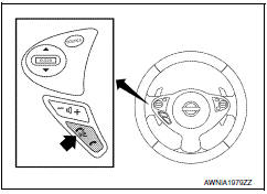
- Press and hold the steering wheel audio control switch
 (PHONE/SEND) button for at least 5
seconds. The Bluetooth system will begin to play a verbal prompt.
(PHONE/SEND) button for at least 5
seconds. The Bluetooth system will begin to play a verbal prompt.
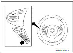
- While the prompt is playing, press and hold the steering wheel audio
control switch
 (PHONE/END) button until you
hear the "Diagnostics mode" prompt. The Bluetooth system will sound a
5-second beep.
(PHONE/END) button until you
hear the "Diagnostics mode" prompt. The Bluetooth system will sound a
5-second beep. - While the beep is sounding, press and hold the steering wheel
audio control switch
 (PHONE/END) button again
until you hear prompts.
(PHONE/END) button again
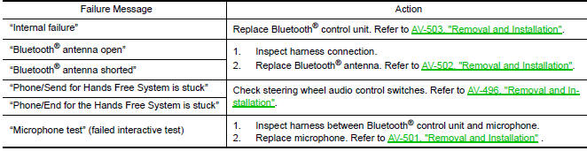
until you hear prompts. - The Bluetooth system has now entered into the diagnostic mode. Results of the diagnostic checks will be verbalized to the technician. Refer to AV-362, "Work Flow".
- After the failure records are reported, an interactive microphone test will be performed. Follow the voice prompt. If the microphone test fails, refer to AV-362, "Work Flow".
Work Flow
 Diagnosis system (AV control unit)
Diagnosis Description
MULTIFUNCTION SWITCH AND PRESET SWITCH SELF-DIAGNOSIS FUNCTION
The ON/OFF operation (continuity) of each switch in the multifunction switch
and preset switch can be checked.
...

Other materials:
Interior room lamp
Wiring Diagram
...
TCM branch line circuit
Diagnosis Procedure
1.CHECK CONNECTOR
Turn the ignition switch OFF.
Disconnect the battery cable from the negative terminal.
Check the following terminals and connectors for damage, bend and
loose connection (unit side and connector
side).
TCM
Harness connector F1
Harness con ...
Magnet clutch
Description
SYSTEM DESCRIPTION
A/C auto amp. controls A/C compressor operation by ambient temperature and
signal from ECM.
Low Temperature Protection Control
A/C auto amp. will turn the A/C compressor ON or OFF as determined
by a signal detected by ambient sensor.
When ambient temperatur ...
Nissan Maxima Owners Manual
- Illustrated table of contents
- Safety-Seats, seat belts and supplemental restraint system
- Instruments and controls
- Pre-driving checks and adjustments
- Monitor, climate, audio, phone and voice recognition systems
- Starting and driving
- In case of emergency
- Appearance and care
- Do-it-yourself
- Maintenance and schedules
- Technical and consumer information
Nissan Maxima Service and Repair Manual

0.0059