Nissan Maxima Service and Repair Manual: P0130, P0150 A/F sensor 1
Description
The air fuel ratio (A/F) sensor 1 is a planar one-cell limit current sensor.
The sensor element of the A/F sensor 1 is composed an electrode layer, which transports ions. It has a heater in the element.
The sensor is capable of precise measurement = 1, but also in the lean and rich range. Together with its control electronics, the sensor outputs a clear, continuous signal throughout a wide range.
The exhaust gas components diffuse via the diffusion layer at the sensor cell. An electrode layer is applied voltage, and this current relative oxygen density in lean. Also this current relative hydrocarbon density in rich.
Therefore, the A/F sensor 1 is able to indicate air fuel ratio by this electrode layer of current. In addition, a heater is integrated in the sensor to ensure the required operating temperature of about 800C (1,472F).
DTC Logic
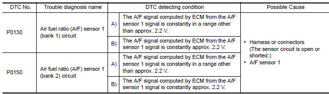
DTC DETECTION LOGIC
To judge malfunctions, the diagnosis checks that the A/F signal computed by ECM from the A/F sensor 1 signal fluctuates according to fuel feedback control
DTC CONFIRMATION PROCEDURE
1.PRECONDITIONING
If DTC Confirmation Procedure has been previously conducted, always perform the following before conducting the next test.
- Turn ignition switch OFF and wait at least 10 seconds.
- Turn ignition switch ON.
- Turn ignition switch OFF and wait at least 10 seconds.
TESTING CONDITION: Before performing the following procedure, confirm that battery voltage is more than 11 V at idle.
2.PERFORM DTC CONFIRMATION PROCEDURE FOR MALFUNCTION A
- Start engine and warm it up to normal operating temperature.
- Let it idle for 2 minutes.
- Check 1st trip DTC
3.CHECK AIR FUEL RATIO (A/F) SENSOR 1 FUNCTION
- Start engine and warm it up to normal operating temperature.
- Select "A/F SEN1 (B1)" or "A/F SEN1 (B2)" in "DATA MONITOR" mode with CONSULT.
- Check "A/F SEN1 (B1)" or "A/F SEN1 (B2)" indication.
4.PERFORM DTC CONFIRMATION PROCEDURE FOR MALFUNCTION B-I
- Select "A/F SEN1 (B1) P1276" (for DTC P0130) or "A/F SEN1 (B2) P1286" (for DTC P0150) of "A/F SEN1" in "DTC WORK SUPPORT" mode with CONSULT.
- Touch "START".
- When the following conditions are met, "TESTING" will be displayed on the CONSULT screen.
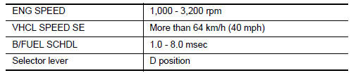
If "TESTING" is not displayed after 20 seconds, retry from step 2.
CAUTION: Always drive vehicle at a safe speed.
5.PERFORM DTC CONFIRMATION PROCEDURE FOR MALFUNCTION B-II
Release accelerator pedal fully.
NOTE: Never apply brake when releasing the accelerator pedal.
6.PERFORM DTC CONFIRMATION PROCEDURE FOR MALFUNCTION B-III
Touch "SELF-DIAG RESULT".
7.PERFORM COMPONENT FUNCTION CHECK FOR MALFUNCTION B
Perform component function check. Refer to EC-220, "Component Function Check".
NOTE: Use component function check to check the overall function of the A/F sensor 1 circuit. During this check, a 1st trip DTC might not be confirmed.
Component Function Check
1.PERFORM COMPONENT FUNCTION CHECK
With GST
- Start engine and warm it up to normal operating temperature.
- Drive the vehicle at a speed of 80 km/h (50 MPH) for a few minutes in the suitable gear position.
- Set D position, then release the accelerator pedal fully until the
vehicle speed decreases to 50 km/h (31
MPH).
CAUTION:
Always drive vehicle at a safe speed.
NOTE: Never apply brake when releasing the accelerator pedal.
- Repeat steps 2 and 3 for five times.
- Stop the vehicle and turn ignition switch OFF.
- Wait at least 10 seconds and restart engine.
- Repeat steps 2 and 3 for five times.
- Stop the vehicle and connect GST to the vehicle.
- Check 1st trip DTC.
Diagnosis Procedure
1.CHECK GROUND CONNECTION
- Turn ignition switch OFF.
- Check ground connection E9. Refer to Ground Inspection
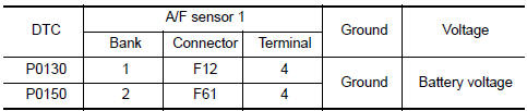
2.CHECK AIR FUEL RATIO (A/F) SENSOR 1 POWER SUPPLY CIRCUIT
- Disconnect A/F sensor 1 harness connector.
- Turn ignition switch ON.
- Check the voltage between A/F sensor 1 harness connector and ground.
3.DETECT MALFUNCTIONING PART
Check the following.
- IPDM E/R harness connector F10
- 15 A fuse (No. 37)
- Harness for open or short between A/F sensor 1 and fuse
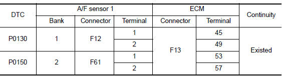
4.CHECK A/F SENSOR 1 INPUT SIGNAL CIRCUIT FOR OPEN AND SHORT
- Turn ignition switch OFF.
- Disconnect ECM harness connector.
- Check the continuity between A/F sensor 1 harness connector and ECM harness connector.
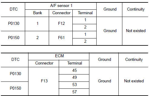
- Check the continuity between A/F sensor 1 harness connector and ground, or ECM harness connector and ground.
- Also check harness for short to power.
5.CHECK INTERMITTENT INCIDENT
6.REPLACE AIR FUEL RATIO (A/F) SENSOR 1
Replace malfunctioning air fuel ratio (A/F) sensor 1.
CAUTION:
- Discard any A/F sensor which has been dropped from a height of more than 0.5 m (19.7 in) onto a hard surface such as a concrete floor; use a new one.
- Before installing new A/F sensor, clean exhaust system threads using Oxygen Sensor Thread Cleaner [commercial service tool (J-43897-18 or J-43897-12)] and approved anti-seize lubricant (commercial service tool).
 P0128 thermostat function
DTC Logic
DTC DETECTION LOGIC
NOTE:
If DTC P0128 is displayed with DTC P0300, P0301, P0302, P0303, P0304, P0305 or
P0306, first perform
the trouble diagnosis for DTC P0300, P0301, P0302, P0303 ...
 P0131, P0151 A/F sensor 1
Description
The air fuel ratio (A/F) sensor 1 is a planar one-cell limit current sensor.
The sensor element of the A/F sensor 1 is composed an electrode
layer, which transports ions. It has ...
Other materials:
Squeak and rattle trouble diagnoses
Work Flow
CUSTOMER INTERVIEW
Interview the customer if possible, to determine the conditions that exist
when the noise occurs. Use the Diagnostic Worksheet during the interview to
document the facts and conditions when the noise occurs and any customer's
comments; refer to RF-144, "Diagnos ...
Cluster lid A
Removal and Installation
REMOVAL
Using a suitable tool, gently remove the instrument side finisher
LH (1).
Remove the instrument lower panel LH (1).
Open the fuse block cover and remove the instrument lower panel
screw (A).
Disconnect the harness connectors and aspirator hose. ...
Refrigerant pressure sensor
Removal and Installation
REMOVAL
Discharge the refrigerant. Refer to HA-28, "Recycle Refrigerant".
Remove the core support upper cover.
Disconnect the harness connector from the refrigerant pressure
sensor.
Remove the refrigerant pressure sensor.
CAUTION:
Cap or wrap the ...
Nissan Maxima Owners Manual
- Illustrated table of contents
- Safety-Seats, seat belts and supplemental restraint system
- Instruments and controls
- Pre-driving checks and adjustments
- Monitor, climate, audio, phone and voice recognition systems
- Starting and driving
- In case of emergency
- Appearance and care
- Do-it-yourself
- Maintenance and schedules
- Technical and consumer information
Nissan Maxima Service and Repair Manual

0.0058