Nissan Maxima Service and Repair Manual: P0128 thermostat function
DTC Logic
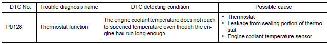
DTC DETECTION LOGIC
NOTE: If DTC P0128 is displayed with DTC P0300, P0301, P0302, P0303, P0304, P0305 or P0306, first perform the trouble diagnosis for DTC P0300, P0301, P0302, P0303, P0304, P0305, P0306.
Engine coolant temperature has not risen enough to open the thermostat even though the engine has run long enough.
This is due to a leakage in the seal or the thermostat being stuck open.
DTC CONFIRMATION PROCEDURE
NOTE: Never refuel before and during the following procedure.
1.PRECONDITIONING-I
If DTC Confirmation Procedure has been previously conducted, always perform the following procedure before conducting the next test.
- Turn ignition switch OFF and wait at least 10 seconds.
- Turn ignition switch ON.
- Turn ignition switch OFF and wait at least 10 seconds.
2.PRECONDITIONING-II
With CONSULT
- Turn ignition switch ON.
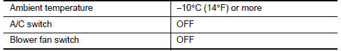
- Check the following conditions:
- Select "DATA MONITOR" mode of "ENGINE" using CONSULT.
- Check the following conditions:

3.PERFORM DTC CONFIRMATION PROCEDURE-I
With CONSULT
- Start engine.
- Drive the vehicle until the following condition is satisfied
CAUTION: Always drive vehicle at safe speed.
- STEP 1
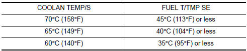
Drive the vehicle under the conditions instructed below until the difference between "COOLAN TEMP/S" and "FUEL T/TMP SE" becomes at least 25C (45F).
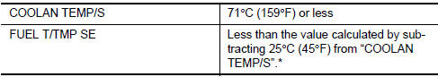
*: Example
- STEP 2
Drive the vehicle at 50 km/h (32 MPH) or more with the difference between
"COOLAN TEMP/S" and "FUEL
T/TMP SE" maintained at 25C (45F) or more.
NOTE: Keep the accelerator pedal as steady as possible during cruising.
- STEP 3
Drive the vehicle at 50 km/h (32 MPH) or more until "COOLAN TEMP/S"
increases by 7C (13F).
NOTE: Keep the accelerator pedal as steady as possible during cruising.
4.PERFORM DTC CONFIRMATION PROCEDURE-II
With CONSULT
- Drive the vehicle until the following condition is satisfied.

CAUTION: Always drive vehicle at safe speed.
- Check 1st trip DTC.
Diagnosis Procedure
1.CHECK ENGINE COOLANT TEMPERATURE SENSOR
2.CHECK THERMOSTAT
Check thermostat.
Component Inspection
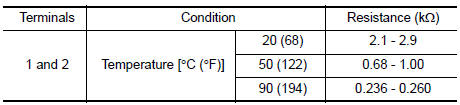
1.CHECK ENGINE COOLANT TEMPERATURE SENSOR
- Turn ignition switch OFF.
- Disconnect engine coolant temperature sensor harness connector.
- Remove engine coolant temperature sensor. Refer to CO-24, "Removal and Installation".
- Check resistance between engine coolant temperature sensor terminals as per the following.
 P0127 IAT sensor
Description
The intake air temperature sensor is built-into the mass air flow sensor
(1). The sensor detects intake air temperature and transmits a
signal to the ECM.
The temperature sensi ...
 P0130, P0150 A/F sensor 1
Description
The air fuel ratio (A/F) sensor 1 is a planar one-cell limit current sensor.
The sensor element of the A/F sensor 1 is composed an electrode
layer, which transports ions. It has ...
Other materials:
Audio antenna
Location of Antenna
AV control unit
AV control unit antenna feeder
In-line connectors M103, M501
Antenna amp.
Window antenna
Satellite radio antenna feeder
Satellite radio antenna
Window Antenna Repair
ELEMENT CHECK
Attach probe circuit tester (ohm setting) to antenna ...
Basic inspection
DIAGNOSIS AND REPAIR WORKFLOW
Work Flow
OVERALL SEQUENCE
DETAILED FLOW
1. GET INFORMATION FOR SYMPTOM
Get the detailed information from the customer about the symptom (the
condition and the environment when
the incident/malfunction occurred).
2. CHECK DTC
Check DTC for BCM and IPDM ...
Lighting & turn signal switch
Removal and Installation
NOTE: The lighting and turn signal switch is
integral with the combination switch assembly.
REMOVAL
Unlock steering wheel.
CAUTION:
Before servicing, disconnect both battery terminals and wait
at least three minutes
Do not use air tools or electric tools ...
Nissan Maxima Owners Manual
- Illustrated table of contents
- Safety-Seats, seat belts and supplemental restraint system
- Instruments and controls
- Pre-driving checks and adjustments
- Monitor, climate, audio, phone and voice recognition systems
- Starting and driving
- In case of emergency
- Appearance and care
- Do-it-yourself
- Maintenance and schedules
- Technical and consumer information
Nissan Maxima Service and Repair Manual

0.0058