Nissan Maxima Service and Repair Manual: P0127 IAT sensor
Description
The intake air temperature sensor is built-into the mass air flow sensor (1). The sensor detects intake air temperature and transmits a signal to the ECM.
The temperature sensing unit uses a thermistor which is sensitive to the change in temperature. Electrical resistance of the thermistor decreases in response to the rise in temperature.
<Reference data>
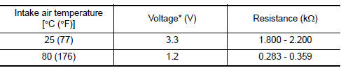
*: These data are reference values and are measured between ECM terminals 50 (Intake air temperature sensor) and 56 (Sensor ground).
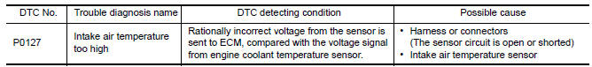
DTC Logic
DTC DETECTION LOGIC
DTC CONFIRMATION PROCEDURE
1.PRECONDITIONING
If DTC Confirmation Procedure has been previously conducted, always perform the following before conducting the next test.
- Turn ignition switch OFF and wait at least 10 seconds.
- Turn ignition switch ON.
- Turn ignition switch OFF and wait at least 10 seconds.
TESTING CONDITION: This test may be conducted with the drive wheels lifted in the shop or by driving the vehicle. If a road test is expected to be easier, it is unnecessary to lift the vehicle.
2.PERFORM DTC CONFIRMATION PROCEDURE
With CONSULT
- Wait until engine coolant temperature is less than 90C (194F)
- Turn ignition switch ON.
- Select "DATA MONITOR" mode with CONSULT.
- Check the engine coolant temperature.
- If the engine coolant temperature is not less than 90C (194F), turn ignition switch OFF and cool down engine.
NOTE: Perform the following steps before engine coolant temperature is above 90C (194F).
- Turn ignition switch ON.
- Select "DATA MONITOR" mode with CONSULT.
- Start engine.
- Hold vehicle speed at more than 70 km/h (43 MPH) for 100 consecutive seconds. CAUTION: Always drive vehicle at a safe speed.
- Check 1st trip DTC.
With GST
Follow the procedure "With CONSULT" above.
Diagnosis Procedure
1.CHECK GROUND CONNECTION
- Turn ignition switch OFF.
- Check ground connection E9.
2.CHECK INTAKE AIR TEMPERATURE SENSOR
3.CHECK INTERMITTENT INCIDENT
Component Inspection
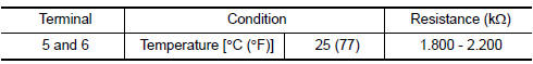
1.CHECK INTAKE AIR TEMPERATURE SENSOR
- Turn ignition switch OFF.
- Disconnect mass air flow sensor harness connector.
- Check resistance between mass air flow sensor terminals as per the following.
 P0125 ECT sensor
Description
The engine coolant temperature sensor is used to detect the engine
coolant temperature. The sensor modifies a voltage signal from the
ECM. The modified signal returns to the ECM a ...
 P0128 thermostat function
DTC Logic
DTC DETECTION LOGIC
NOTE:
If DTC P0128 is displayed with DTC P0300, P0301, P0302, P0303, P0304, P0305 or
P0306, first perform
the trouble diagnosis for DTC P0300, P0301, P0302, P0303 ...
Other materials:
Precaution
Precaution for Supplemental Restraint System (SRS) "AIR BAG" and
"SEAT BELT PRE-TENSIONER"
The Supplemental Restraint System such as "AIR BAG" and "SEAT BELT
PRE-TENSIONER", used along with a front seat belt, helps to reduce the risk
or severity of injury to the driver and front passenger for ...
Sun visors
To block glare from the front, swing down the
sun visor.
To block glare from the side, remove the sun
visor from the center mount and swing the
visor to the side.
Slide the extension sun visor in or out as
needed.
CAUTION
Do not store the sun visor before returning
the exte ...
Steering column
Disassembly and Assembly
The steering column assembly without electric motor is not serviceable and
must be replaced as an assembly.
With Electric Motor
Steering column assembly
Telescope motor
Telescope motor link bracket
Tilt motor
Tilt motor bolt cap
DISASSEMBLY
Remo ...
Nissan Maxima Owners Manual
- Illustrated table of contents
- Safety-Seats, seat belts and supplemental restraint system
- Instruments and controls
- Pre-driving checks and adjustments
- Monitor, climate, audio, phone and voice recognition systems
- Starting and driving
- In case of emergency
- Appearance and care
- Do-it-yourself
- Maintenance and schedules
- Technical and consumer information
Nissan Maxima Service and Repair Manual

0.0055