Nissan Maxima Service and Repair Manual: Compass
Description
DESCRIPTION
With the ignition switch in the ON position, and the mode (N) switch ON, the compass display will indicate the direction the vehicle is heading.
Vehicle direction is displayed as follows:
- N: north
- E: east
- S: south
- W: west
ZONE VARIATION SETTING PROCEDURE
The difference between magnetic north and geographical north can sometimes be great enough to cause false compass readings. This difference is known as variance. In order for the compass to operate properly (accurately) in a particular zone, the zone variation must be calibrated using the following procedure.
Zone Variation Chart
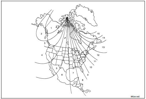
- Determine your location on the zone map.
- Turn the ignition switch to the ON position.
- Hold the mode (N) switch down until the current zone number is displayed.
- Press the mode (N) switch repeatedly until the desired zone number appears in the display.
Compass will exit zone setting mode and display correct heading automatically.
NOTE:
Use zone number 5 for Hawaii.
CALIBRATION PROCEDURE
The compass display is equipped with an automatic correction function. If the compass display reads "C" or the direction is not shown correctly, perform the correction procedure below.
- Hold the mode (N) switch until the display reads "C".
- Drive the vehicle slowly in a circle, in an open, safe place. The initial calibration is completed in about three turns.
NOTE:
In places where the terrestrial magnetism is extremely disturbed, the initial correction may start automatically.
 Meter system
METER SYSTEM : System Diagram
METER SYSTEM : System Description
COMBINATION METER
Speedometer, odo/trip meter, tachometer, fuel gauge, water
temperature gauge and information display are
...
 Diagnosis system (meter)
Diagnosis Description
SELF-DIAGNOSIS MODE
Odo/trip meter and information display segment operation can be
checked in self-diagnosis mode.
Meters/gauges can be checked in self-diagnosis mode. ...
Other materials:
Inspection and adjustment
BASIC INSPECTION
BASIC INSPECTION : Special Repair Requirement
1.INSPECTION START
Check service records for any recent repairs that may indicate a
related malfunction, or a current need for
scheduled maintenance.
Open engine hood and check the following:
Harness connectors fo ...
Wiring diagram
SUNROOF SYSTEM
Wiring Diagram
...
Symptom diagnosis
ADP SYSTEM SYMPTOMS
Symptom Table
SYMPTOM 1
SYMPTOM 2
SYMPTOM 3
SYMPTOM 4
SYMPTOM 5
NORMAL OPERATING CONDITION
Description
The following symptoms are normal operations, and they do not indicate a
malfunction.
...
Nissan Maxima Owners Manual
- Illustrated table of contents
- Safety-Seats, seat belts and supplemental restraint system
- Instruments and controls
- Pre-driving checks and adjustments
- Monitor, climate, audio, phone and voice recognition systems
- Starting and driving
- In case of emergency
- Appearance and care
- Do-it-yourself
- Maintenance and schedules
- Technical and consumer information
Nissan Maxima Service and Repair Manual

0.0056