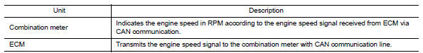
Nissan Maxima Service and Repair Manual: Meter system
METER SYSTEM : System Diagram
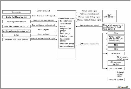
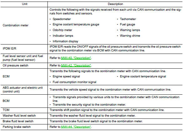
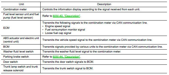
METER SYSTEM : System Description
COMBINATION METER
- Speedometer, odo/trip meter, tachometer, fuel gauge, water temperature gauge and information display are controlled by the unified meter control unit, which is built into the combination meter.
- Warning and indicator lamps are controlled by the unified meter control unit and by components connected directly to the combination meter.
- Digital meter is adopted for odo/trip meter.* *The record of the odometer is kept even if the battery cable is disconnected. The record of the trip meter is erased when the battery cable is disconnected.
- Odo/trip meter and information display segments can be checked in diagnosis mode.
- Meter/gauge can be checked in diagnosis mode.
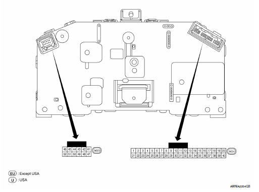
METER SYSTEM : Arrangement of Combination Meter
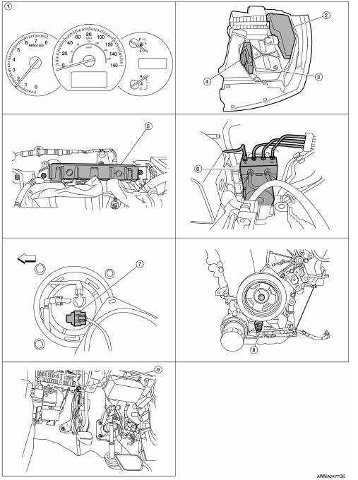
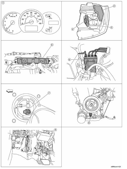
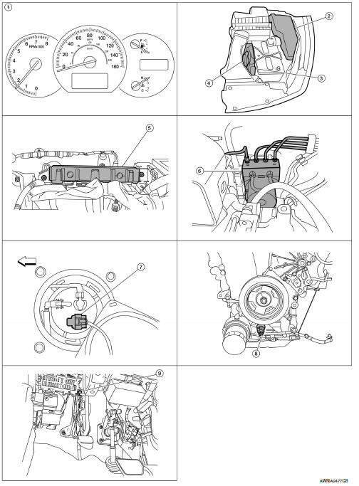
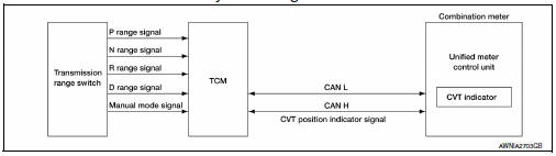
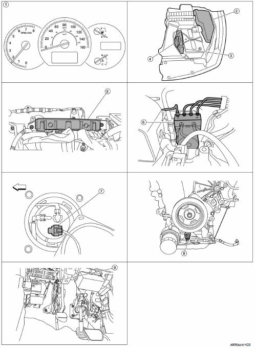
METER SYSTEM : Component Parts Location
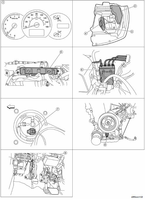
- Combination meter M23, M24
- IPDM E/R E17, E18, E201, F10
- ECM E10
- TCM F15
- BCM M18, M19, M20, M21 (view with instrument panel removed)
- ABS actuator and electric unit (control unit) E26
- Fuel level sensor unit and fuel pump (fuel level sensor) B42 (view with rear seat and inspection hole cover removed) ⇐: Front
- Oil pressure switch F41 (view with engine removed)
- Parking brake switch E35 (view with instrument lower cover LH removed)
METER SYSTEM : Component Description
SPEEDOMETER
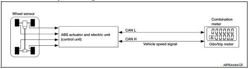
SPEEDOMETER : System Diagram
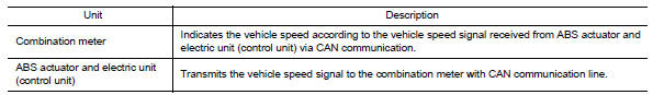
SPEEDOMETER : System Description
The ABS actuator and electric unit (control unit) provides a vehicle speed signal to the combination meter via CAN communication lines.
SPEEDOMETER : Component Parts Location

- Combination meter M23, M24
- IPDM E/R E17, E18, E201, F10
- ECM E10
- TCM F15
- BCM M18, M19, M20, M21 (view with instrument panel removed)
- ABS actuator and electric unit (control unit) E26
- Fuel level sensor unit and fuel pump
(fuel level sensor) B42 (view with rear
seat and inspection hole cover removed)
 : Front
 - Oil pressure switch F41 (view with engine removed)
- Parking brake switch E35 (view with instrument lower cover LH removed)
SPEEDOMETER : Component Description
TACHOMETER
TACHOMETER : System Diagram
TACHOMETER : System Description
The tachometer indicates engine speed in revolutions per minute (RPM).
The ECM provides an engine speed signal to the combination meter via CAN communication lines.
TACHOMETER : Component Parts Location
- Combination meter M23, M24
- IPDM E/R E17, E18, E201, F10
- ECM E10
- TCM F15
- BCM M18, M19, M20, M21 (view with instrument panel removed)
- ABS actuator and electric unit (control unit) E26
- Fuel level sensor unit and fuel pump
(fuel level sensor) B42 (view with rear
seat and inspection hole cover removed)
 : Front
 - Oil pressure switch F41 (view with engine removed)
- Parking brake switch E35 (view with instrument lower cover LH removed)
TACHOMETER : Component Description
ENGINE COOLANT TEMPERATURE GAUGE
ENGINE COOLANT TEMPERATURE GAUGE : System Diagram
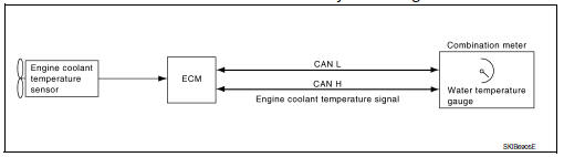
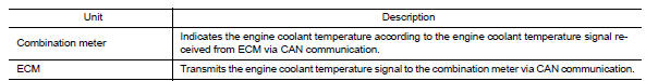
ENGINE COOLANT TEMPERATURE GAUGE : System Description
The water temperature gauge indicates the engine coolant temperature.
The ECM provides an engine coolant temperature signal to the combination meter via CAN communication lines.
ENGINE COOLANT TEMPERATURE GAUGE : Component Parts Location
- Combination meter M23, M24
- IPDM E/R E17, E18, E201, F10
- ECM E10
- TCM F15
- BCM M18, M19, M20, M21 (view with instrument panel removed)
- ABS actuator and electric unit (control unit) E26
- Fuel level sensor unit and fuel pump
(fuel level sensor) B42 (view with rear
seat and inspection hole cover removed)
 : Front
 - Oil pressure switch F41 (view with engine removed)
- Parking brake switch E35 (view with instrument lower cover LH removed)
ENGINE COOLANT TEMPERATURE GAUGE : Component Description
FUEL GAUGE
FUEL GAUGE : System Diagram
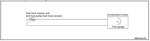
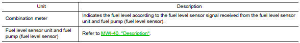
FUEL GAUGE : System Description
The fuel gauge indicates the approximate fuel level in the fuel tank.
The fuel gauge is regulated by the unified meter control unit and a variable resistor signal supplied by the fuel level sensor unit and fuel pump (fuel level sensor).
FUEL GAUGE : Component Parts Location
- Combination meter M23, M24
- IPDM E/R E17, E18, E201, F10
- ECM E10
- TCM F15
- BCM M18, M19, M20, M21 (view with instrument panel removed)
- ABS actuator and electric unit (control unit) E26
- Fuel level sensor unit and fuel pump
(fuel level sensor) B42 (view with rear
seat and inspection hole cover removed)
 : Front
 - Oil pressure switch F41 (view with engine removed)
- Parking brake switch E35 (view with instrument lower cover LH removed)
FUEL GAUGE : Component Description
ODO/TRIP METER
ODO/TRIP METER : System Diagram
ODO/TRIP METER : System Description
The vehicle speed signal and the memory signals from the meter memory circuit are processed by the combination meter and the mileage is displayed.
HOW TO CHANGE THE DISPLAY FOR ODO/TRIP METER Refer to Owner's Manual for odo/trip meter operating instructions.
ODO/TRIP METER : Component Parts Location

- Combination meter M23, M24
- IPDM E/R E17, E18, E201, F10
- ECM E10
- TCM F15
- BCM M18, M19, M20, M21 (view with instrument panel removed)
- ABS actuator and electric unit (control unit) E26
- Fuel level sensor unit and fuel pump
(fuel level sensor) B42 (view with rear
seat and inspection hole cover removed)
 : Front
 - Oil pressure switch F41 (view with engine removed)
- Parking brake switch E35 (view with instrument lower cover LH removed)
ODO/TRIP METER : Component Description
SHIFT POSITION INDICATOR
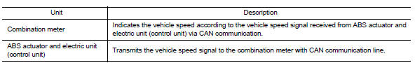
SHIFT POSITION INDICATOR : System Diagram
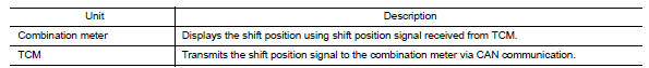
SHIFT POSITION INDICATOR : System Description
The TCM receives CVT indicator signals from the transmission range switch. The TCM then sends CVT position indicator signals to the combination meter via CAN communication lines. The combination meter indicates the received shift position.
SHIFT POSITION INDICATOR : Component Parts Location
- Combination meter M23, M24
- IPDM E/R E17, E18, E201, F10
- ECM E10
- TCM F15
- BCM M18, M19, M20, M21 (view with instrument panel removed)
- ABS actuator and electric unit (control unit) E26
- Fuel level sensor unit and fuel pump
(fuel level sensor) B42 (view with rear
seat and inspection hole cover removed)
 : Front
 - Oil pressure switch F41 (view with engine removed)
- Parking brake switch E35 (view with instrument lower cover LH removed)
SHIFT POSITION INDICATOR : Component Description
WARNING LAMPS/INDICATOR LAMPS
WARNING LAMPS/INDICATOR LAMPS : System Diagram
WARNING LAMPS/INDICATOR LAMPS : System Description
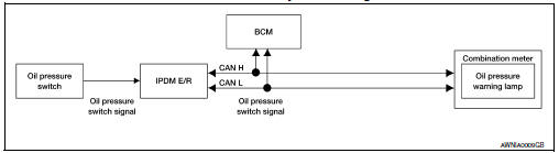
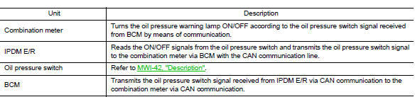
OIL PRESSURE WARNING LAMP
The oil pressure warning lamp is controlled by the IPDM E/R (intelligent power distribution module engine room).
Low oil pressure causes the oil pressure switch to provide a ground signal to the IPDM E/R. The IPDM E/R then signals the combination meter (unified meter control unit) via the CAN communication lines and ground is provided to the oil pressure warning lamp.
When power and ground are supplied, the oil pressure warning lamp illuminates.
WARNING LAMPS/INDICATOR LAMPS : Component Parts Location

- Combination meter M23, M24
- IPDM E/R E17, E18, E201, F10
- ECM E10
- TCM F15
- BCM M18, M19, M20, M21 (view with instrument panel removed)
- ABS actuator and electric unit (control unit) E26
- Fuel level sensor unit and fuel pump
(fuel level sensor) B42 (view with rear
seat and inspection hole cover removed)
 : Front
 - Oil pressure switch F41 (view with engine removed)
- Parking brake switch E35 (view with instrument lower cover LH removed)
WARNING LAMPS/INDICATOR LAMPS : Component Description
INFORMATION DISPLAY
INFORMATION DISPLAY : System Diagram
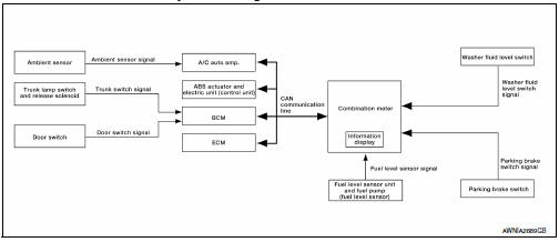
INFORMATION DISPLAY : System Description
FUNCTION
The information display can indicate the following items.
- Outside air temperature
- Trip/fuel consumption readings
- Intelligent Key operation information
- Tire pressure information
- Maintenance information
- Warning/Indication messages (Door ajar, low fuel, low washer fluid, parking brake, cruise control, loose fuel cap, check tire pressure)
OUTSIDE AIR TEMPERATURE INDICATION
The outside air temperature indication is displayed while the ignition switch is in the ON position.
Indication range is between -30 and 55C (-22 and 131F). When outside temperature is less than 3C (37F), display shows ICY. The indicated temperature is not affected by engine heat. It changes only when one of the following conditions exists.
- When vehicle speed is more than approximately 20 km/h (12 MPH).
- The ignition switch has been turned OFF for more than 3.5 hours.
- When outside air temperature is less than the indicated temperature.
MPG
Average fuel consumption indication is calculated using vehicle speed signals from the ABS actuator and electric unit (control unit) and fuel consumption information from the ECM.
MPG/MPH
The average speed mode can be selected to display the average fuel consumption and average speed since last reset. The indications are calculated using vehicle speed signals from the ABS actuator and electric unit (control unit) and fuel consumption information from the ECM
RANGE
The range indication provides the driver with an estimation of the distance that can be driven before refueling.
The range is calculated using signals from the fuel level sensor unit and fuel pump (fuel level sensor) (fuel remaining), ECM (fuel consumption) and vehicle speed signals from the ABS actuator and electric unit (control unit).
TIRE PRESSURE DISPLAY
Displays the individual tire pressure details. The BCM sends the tire pressure signals to the combination meter via CAN communication lines.
DOOR AJAR WARNING
This warning appears when the Intelligent Key is in the vehicle and any door or the trunk is opened.
LOW FUEL WARNING
This warning appears when the fuel level in the fuel tank reaches approximately 12.3 (3 1/4 US gal, 2 3/4 Imp gal). A variable resistor signal is supplied to the combination meter from the fuel level sensor unit and fuel pump (fuel level sensor) to determine the amount of fuel in the fuel tank.
LOOSE FUEL CAP WARNING
The LOOSE FUEL CAP indicator will display in the information display when the fuel-filler cap is not tightened correctly. The indicator will turn off as soon as the ECM detects the fuel-filler cap is properly tightened. The ECM provides a loose fuel cap signal to the combination meter via CAN communication lines.
CHECK TIRE PRESSURE WARNING
The CHECK TIRE PRESSURE indicator will display in the information display when BCM has detected a low tire pressure condition. After 8 seconds, the Tire Pressure Warning Mode will flash and the low tire pressure will be highlighted (one of the four numbers). These two screens will continue to toggle every eight seconds until the low tire pressure condition has been corrected and the vehicle has been driven above 25 km/h (16 MPH).
LOW WINDSHIELD WASHER FLUID WARNING
This warning appears when the windshield washer fluid level is low. When the windshield washer fluid level is low, the washer fluid level switch provides a ground signal to the combination meter (unified meter control unit). The message will be displayed after the ignition switch is turned on for 3 minutes. Once fluid is added, the message will stay on for 30 seconds and then turn off.
PARKING BRAKE INDICATOR
When the ignition switch is in the ON position and the parking brake is depressed, the indicator will turn on.
When the parking brake is depressed, the parking brake switch provides a ground signal to the combination meter (unified meter control unit). Then, when the ignition switch is turned ON and vehicle speed is greater than 5 km/h (3 MPH), the message is displayed.
CRUISE SET INDICATOR
The cruise set indicator message is displayed when the vehicle speed is controlled by the ASCD system. The ECM provides an ASCD ON signal to the combination meter (unified meter control unit) via CAN communication lines.
INFORMATION DISPLAY : Component Parts Location
- Combination meter M23, M24
- IPDM E/R E17, E18, E201, F10
- ECM E10
- TCM F15
- BCM M18, M19, M20, M21 (view with instrument panel removed)
- ABS actuator and electric unit (control unit) E26
- Fuel level sensor unit and fuel pump
(fuel level sensor) B42 (view with rear
seat and inspection hole cover removed)
 : Front
 - Oil pressure switch F41 (view with engine removed)
- Parking brake switch E35 (view with instrument lower cover LH removed)
INFORMATION DISPLAY : Component Description

 Compass
Description
DESCRIPTION
With the ignition switch in the ON position, and the mode (N) switch
ON, the compass display will indicate the direction the vehicle is
heading.
Vehicle direction is dis ...
Other materials:
Steering switch
Removal and Installation
REMOVAL
Remove the driver airbag module. Refer to SR-12, "Removal and
Installation".
Remove the steering wheel audio control switch screws (A).
Release the steering wheel audio control switch harness clips
(B).
Remove the steering wheel audio control switc ...
Doors
When the doors are locked using one of the
following methods, the doors cannot be opened
using the inside or outside door handles. The
doors must be unlocked to open the doors.
WARNING
Before opening any door, always look
for and avoid oncoming traffic.
To help avoid risk of injury or de ...
General maintenance
General maintenance includes those items which
should be checked during normal day-to-day operation.
They are essential for proper vehicle operation.
It is your responsibility to perform these
procedures regularly as prescribed.
Performing general maintenance checks requires
minimal mech ...
Nissan Maxima Owners Manual
- Illustrated table of contents
- Safety-Seats, seat belts and supplemental restraint system
- Instruments and controls
- Pre-driving checks and adjustments
- Monitor, climate, audio, phone and voice recognition systems
- Starting and driving
- In case of emergency
- Appearance and care
- Do-it-yourself
- Maintenance and schedules
- Technical and consumer information
Nissan Maxima Service and Repair Manual

0.0063