Nissan Maxima Service and Repair Manual: IPDM E/R (intelligent power distribution module engine room)
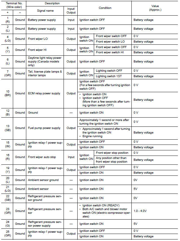
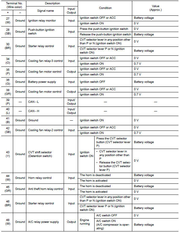
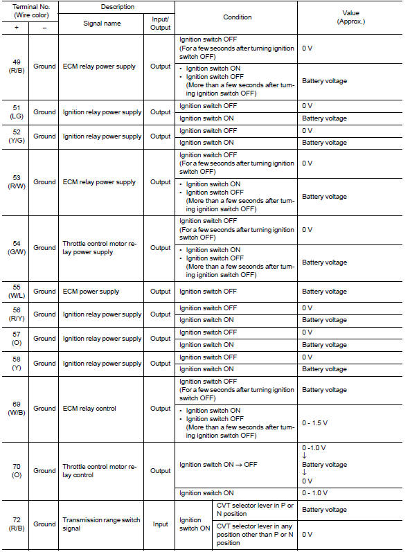
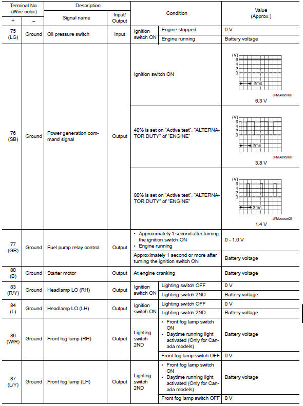
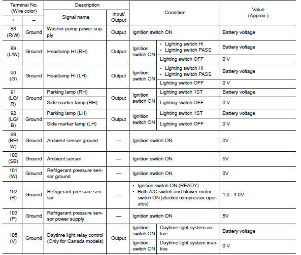
Reference Value
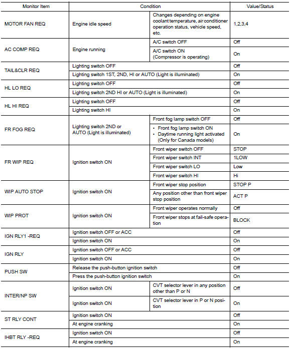
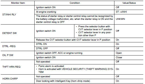
VALUES ON THE DIAGNOSIS TOOL
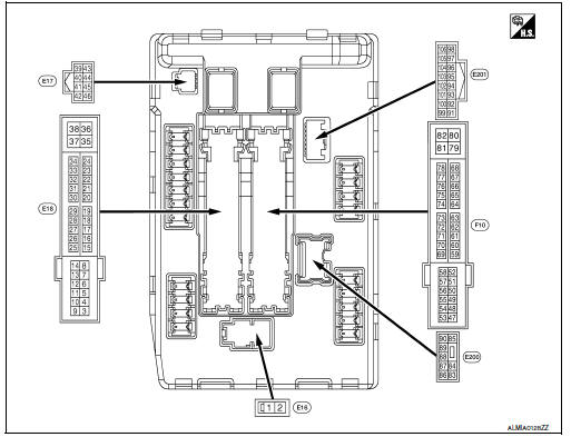
TERMINAL LAYOUT
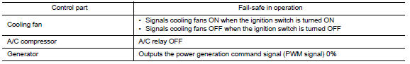
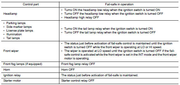
Fail Safe
CAN COMMUNICATION CONTROL When CAN communication with ECM and BCM is impossible, IPDM E/R performs fail-safe control. After CAN communication recovers normally, it also returns to normal control.
If No CAN Communication Is Available With ECM
If No CAN Communication Is Available With BCM
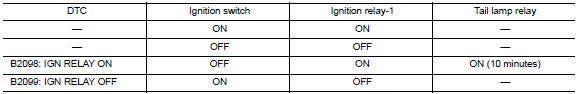
IGNITION RELAY MALFUNCTION DETECTION FUNCTION
-
IPDM E/R monitors the voltage at the contact circuit and excitation coil circuit of the ignition relay-1 inside it.
-
IPDM E/R judges the ignition relay-1 error if the voltage differs between the contact circuit and the excitation coil circuit.
-
If the ignition relay-1 cannot turn OFF due to contact seizure, it activates the tail lamp relay for 10 minutes to alert the user to the ignition relay-1 malfunction when the ignition switch is turned OFF.
NOTE:
The tail lamp turns OFF when the ignition switch is turned ON.
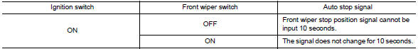
FRONT WIPER CONTROL
IPDM E/R detects front wiper stop position by a front wiper auto stop signal.
When a front wiper auto stop signal is in the conditions listed below, IPDM E/R stops power supply to wiper after repeating a front wiper 10 seconds activation and 20 seconds stop five times.
NOTE:
This operation status can be confirmed on the IPDM E/R "Data Monitor" that displays "BLOCK" for the item "WIP PROT" while the wiper is stopped.
STARTER MOTOR PROTECTION FUNCTION
IPDM E/R turns OFF the starter control relay to protect the starter motor when the starter control relay remains active for 90 seconds.
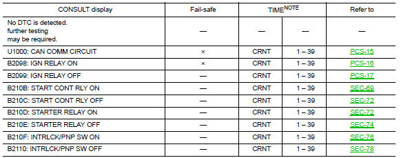
DTC Index
NOTE:
-
The details of TIME display are as follows.
CRNT: The malfunctions that are detected now
-
1 - 39: The number is indicated when it is normal at present and a malfunction was detected in the past. It increases like 0 → 1 → 2 ··* 38 → 39 after returning to the normal condition whenever IGN OFF → ON. It is fixed to 39 until the self-diagnosis results are erased if it is over 39. It returns to 0 when a malfunction is detected again in the process.
 BCM (body control module)
Reference Value
NOTE:
The Signal Tech II Tool (J-50190) can be used
to perform the following functions. Refer to the Signal Tech II
User Guide for additional information.
Activate and dis ...
 Wiring diagram
...
Other materials:
Extended storage switch
The extended storage switch is used when the
vehicle is in transit from the factory. It is located in
the fuse panel to the left of the steering wheel on
the instrument panel. If any electrical equipment
does not operate, ensure the extended storage
switch is pushed fully in place, as shown ...
P1723 speed sensor
Description
The secondary speed sensor detects the revolution of
parking gear and generates a pulse signal. The pulse
signal is sent to the TCM, which converts it into vehicle speed.
The primary speed sensor detects the primary pulley revolution speed and sends a
signal to the TCM.
DTC Lo ...
HomeLink Universal Transceiver
The HomeLink Universal Transceiver provides
a convenient way to consolidate the functions of
up to three individual hand-held transmitters into
one built-in device.
HomeLink Universal Transceiver:
Will operate most radio frequency devices
such as garage doors, gates, home and office
li ...
Nissan Maxima Owners Manual
- Illustrated table of contents
- Safety-Seats, seat belts and supplemental restraint system
- Instruments and controls
- Pre-driving checks and adjustments
- Monitor, climate, audio, phone and voice recognition systems
- Starting and driving
- In case of emergency
- Appearance and care
- Do-it-yourself
- Maintenance and schedules
- Technical and consumer information
Nissan Maxima Service and Repair Manual

0.0056