Nissan Maxima Service and Repair Manual: BCM (body control module)
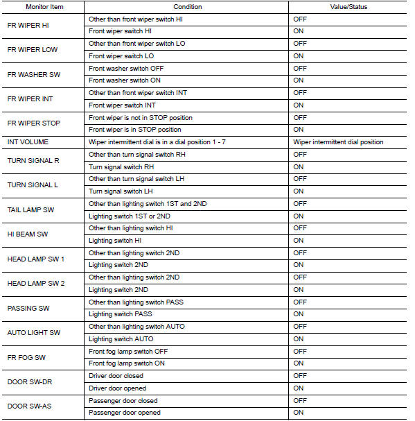
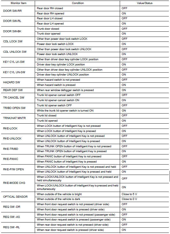
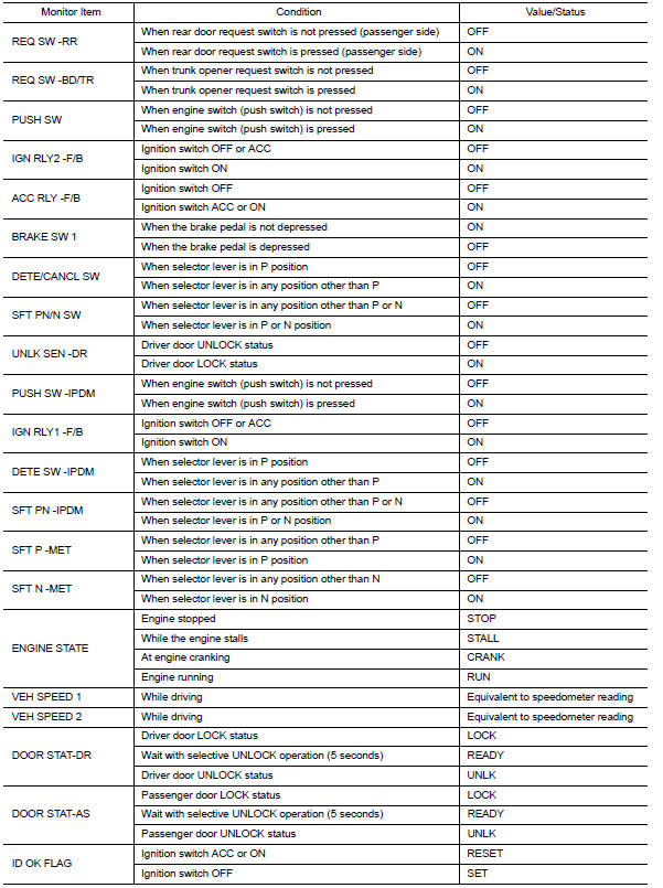
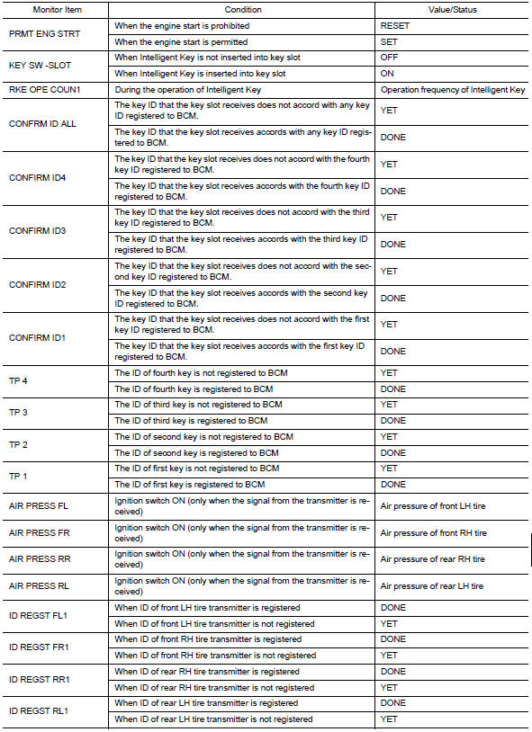
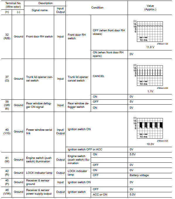
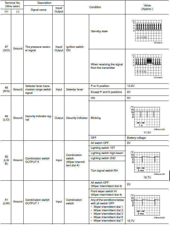
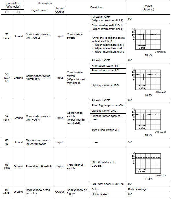
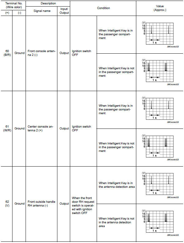
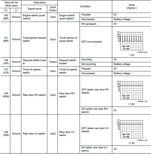
Reference Value
NOTE:
The Signal Tech II Tool (J-50190) can be used to perform the following functions. Refer to the Signal Tech II User Guide for additional information.
-
Activate and display TPMS transmitter IDs
-
Display tire pressure reported by the TPMS transmitter
-
Read TPMS DTCs
-
Register TPMS transmitter IDs
-
Check Intelligent Key relative signal strength
-
Confirm vehicle Intelligent Key antenna signal strength
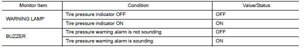
VALUES ON THE DIAGNOSIS TOOL
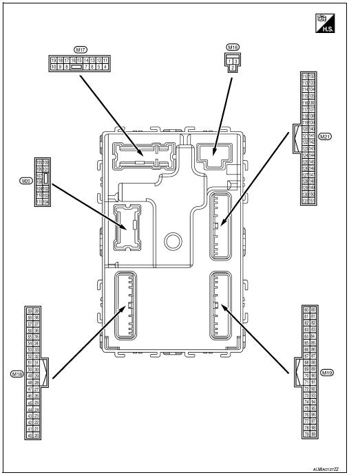
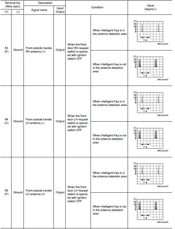
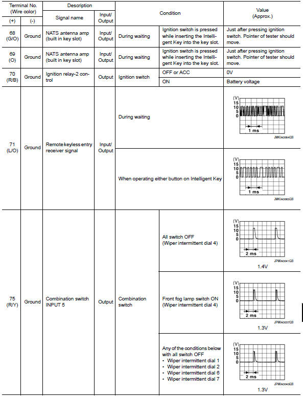
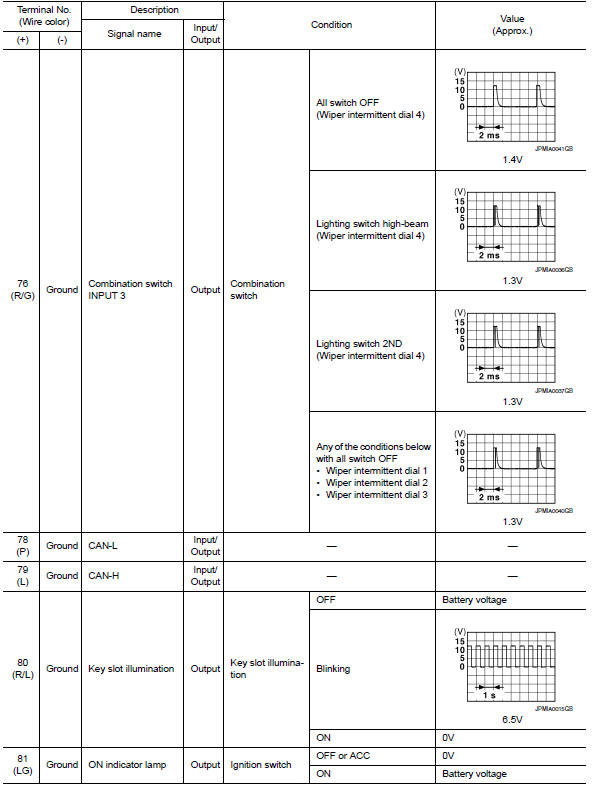
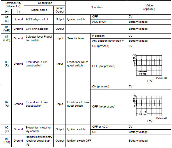
Terminal Layout
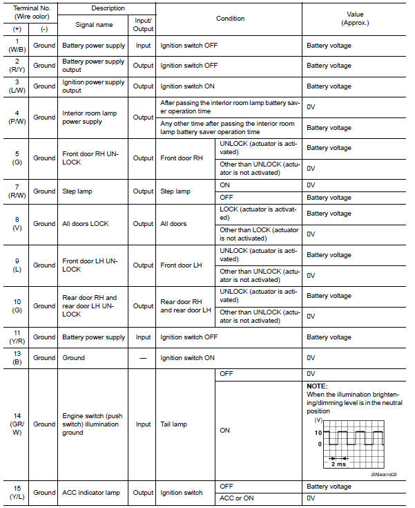
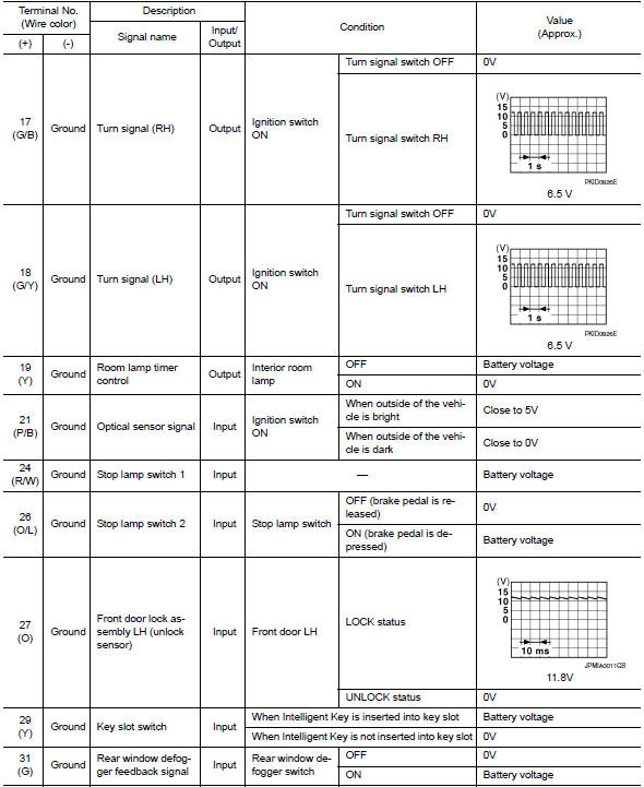
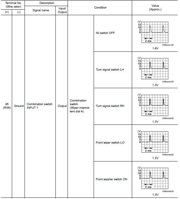
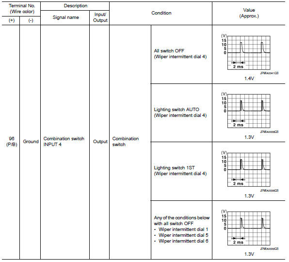
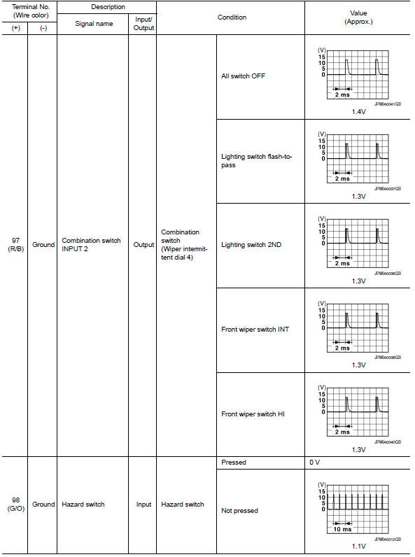
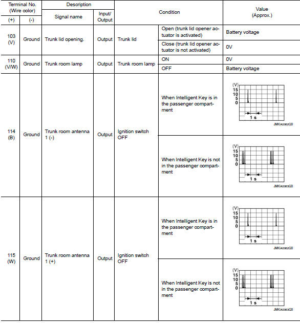
Physical Values
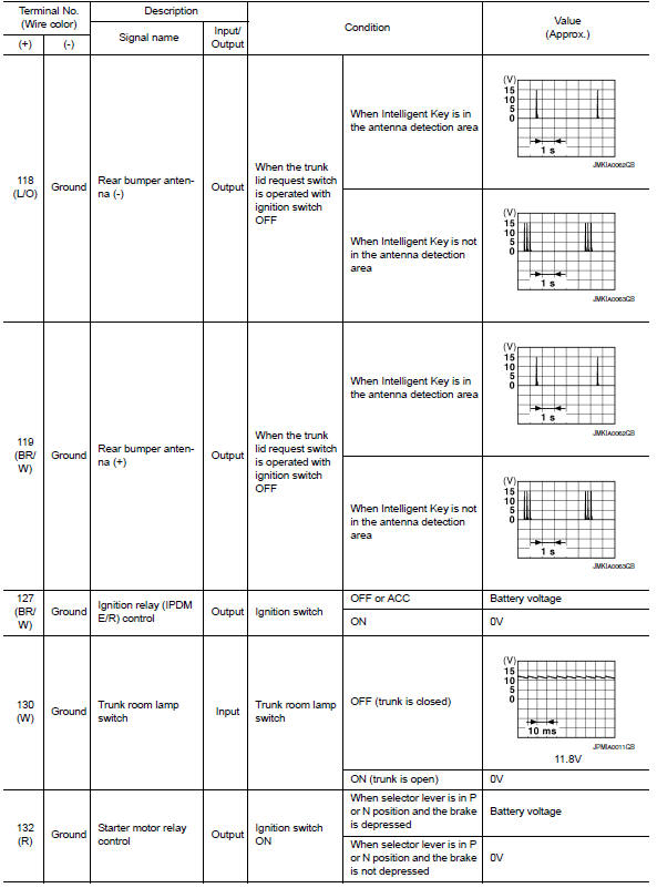
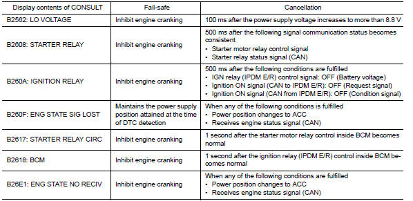
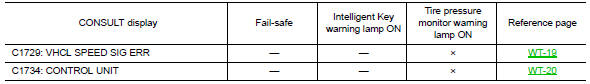
Fail Safe
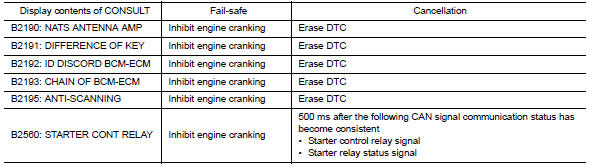
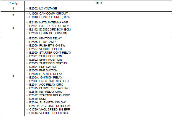
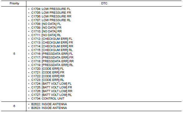
DTC Inspection Priority Chart
If some DTCs are displayed at the same time, perform inspections one by one based on the following priority chart.
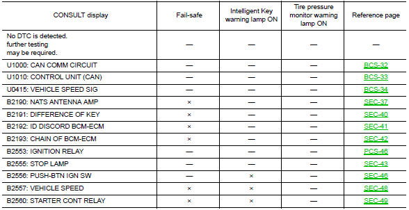
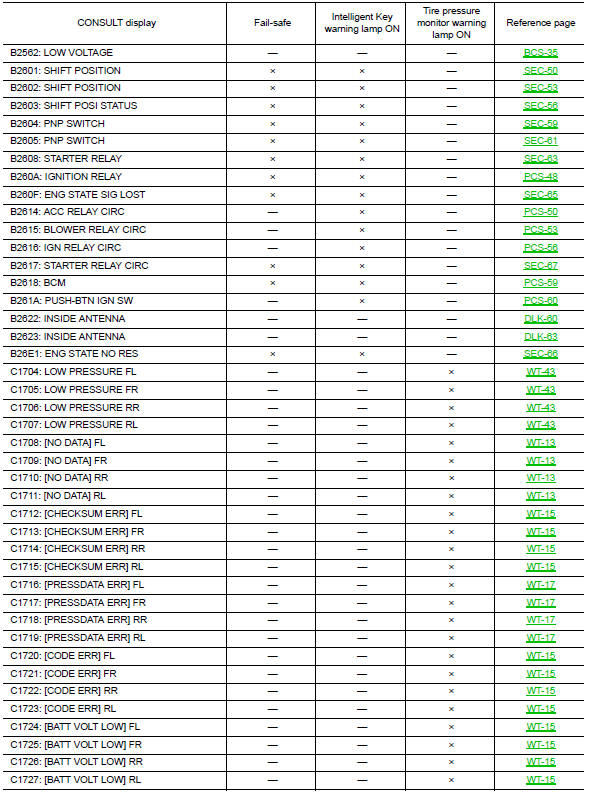
DTC Index
NOTE:
Details of time display
-
CRNT: Displays when there is a malfunction now or after returning to the normal condition until turning ignition switch OFF → ON again.
-
1 - 39: Displayed if any previous malfunction is present when current condition is normal. It increases 1 → 2 → 3...38 → 39 after returning to the normal condition whenever ignition switch OFF → ON. The counter remains at 39 even if the number of cycles exceeds it. It is counted from 1 again when turning ignition switch OFF → ON after returning to the normal condition if the malfunction is detected again.
 Combination meter
Reference Value
VALUES ON THE DIAGNOSIS TOOL
NOTE:
* The monitor will indicate "OFF" even though
the brake warning lamp is on if either of the following conditions exist:
The parking ...
 IPDM E/R (intelligent power distribution module engine room)
Reference Value
VALUES ON THE DIAGNOSIS TOOL
TERMINAL LAYOUT
Fail Safe
CAN COMMUNICATION CONTROL
When CAN communication with ECM and BCM is impossible, IPDM E/R performs
fail-s ...
Other materials:
EVAP control system pressure sensor
Removal and Installation
REMOVAL
Remove rear stabilizer bar clamps and position rear stabilizer bar
aside. Refer to RSU-13, "Removal and Installation".
Disconnect EVAP hose from EVAP canister.
Disconnect EVAP control system pressure sensor.
Remove EVAP control s ...
Front door switch (driver side)
Description
Detects front door LH open/close condition.
Component Function Check
1. CHECK FUNCTION
Select "DOOR SW-FL" in "DATA MONITOR" mode with CONSULT.
Check the front door switch signal under the following conditions
Diagnosis Procedure
1. CHECK FRONT DOOR SWITCH LH CIRCUIT
...
Power supply and ground circuit
Diagnosis Procedure
1.CHECK GROUND CONNECTION-I
Turn ignition switch OFF.
Check ground connection E9. Refer to Ground Inspection
2.CHECK ECM GROUND CIRCUIT FOR OPEN AND SHORT-I
Disconnect ECM harness connector.
Check the continuity between ECM harness connector and ground.
Also che ...
Nissan Maxima Owners Manual
- Illustrated table of contents
- Safety-Seats, seat belts and supplemental restraint system
- Instruments and controls
- Pre-driving checks and adjustments
- Monitor, climate, audio, phone and voice recognition systems
- Starting and driving
- In case of emergency
- Appearance and care
- Do-it-yourself
- Maintenance and schedules
- Technical and consumer information
Nissan Maxima Service and Repair Manual

0.0068