Nissan Maxima Service and Repair Manual: C1121, C1123, C1125, C1127 out ABS sol
Description
The solenoid valve increases, holds or decreases the fluid pressure of each brake caliper according to the signals transmitted by the ABS actuator and electric unit (control unit).
DTC Logic
DTC DETECTION LOGIC
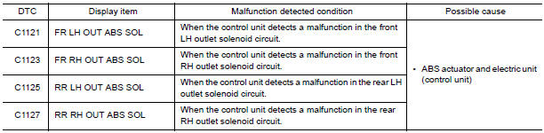
DTC CONFIRMATION PROCEDURE
1.CHECK SELF-DIAGNOSIS RESULTS
Check the self-diagnosis results.

Diagnosis Procedure
1.CONNECTOR INSPECTION
- Turn ignition switch OFF.
- Disconnect ABS actuator and electric unit (control unit) connector.
- Check terminals for deformation, disconnection, looseness, and so on. If any malfunction is found, repair or replace terminals.
- Reconnect connector and perform self-diagnosis.
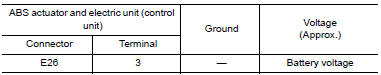
2.CHECK SOLENOID AND ACTUATOR RELAY POWER SUPPLY CIRCUIT
- Turn ignition switch OFF.
- Disconnect ABS actuator and electric unit (control unit) connector.
- Check voltage between ABS actuator and electric unit (control unit) connector E26 terminal 3 and ground.
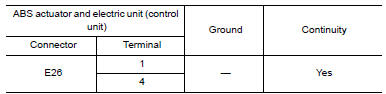
3. CHECK SOLENOID AND ACTUATOR RELAY GROUND CIRCUIT
Check continuity between ABS actuator and electric unit (control unit) connector E26 terminals 1, 4 and ground.
Component Inspection
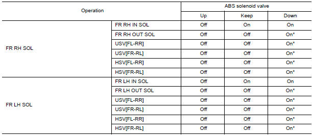
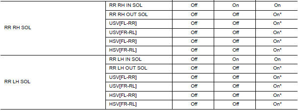
1.CHECK ACTIVE TEST
- Select each test menu item on "ACTIVE TEST".
- On the display, touch "Up", "Keep", and "Down", and check that the system operates as shown in the table below.
Special Repair Requirement
1.ADJUSTMENT OF STEERING ANGLE SENSOR NEUTRAL POSITION
Always perform the neutral position adjustment for the steering angle sensor, when replacing the ABS actuator and electric unit (control unit).
 C1120, C1122, C1124, C1126 in ABS sol
Description
The solenoid valve increases, holds or decreases the fluid pressure of each
brake caliper according to the signals
transmitted by the ABS actuator and electric unit (control unit).
D ...
 C1130, C1131, C1132, C1133, C1136 engine signal
Description
ABS actuator and electric unit (control unit) and ECM exchange the engine
signal with CAN communication
line.
DTC Logic
DTC DETECTION LOGIC
DTC CONFIRMATION PROCEDURE
1.CHECK ...
Other materials:
U1218 AV control unit
DTC Logic
U1219 AV CONTROL UNIT
DTC Logic
U121A AV CONTROL UNIT
DTC Logic
U121B AV CONTROL UNIT
DTC Logic
U121C AV CONTROL UNIT
DTC Logic
...
A-bag branch line circuit
Diagnosis Procedure
WARNING:
Always observe the following items for preventing accidental
activation.
Before servicing, turn ignition switch OFF, disconnect battery negative
terminal, and wait 3 minutes or more. (To discharge backup capacitor.)
Never use unspecified tester or other measu ...
Rapid air pressure loss
Rapid air pressure loss or a "blow-out" can occur
if the tire is punctured or is damaged due to
hitting a curb or pothole. Rapid air pressure loss
can also be caused by driving on under-inflated
tires.
Rapid air pressure loss can affect the handling
and stability of the vehicle, especially a ...
Nissan Maxima Owners Manual
- Illustrated table of contents
- Safety-Seats, seat belts and supplemental restraint system
- Instruments and controls
- Pre-driving checks and adjustments
- Monitor, climate, audio, phone and voice recognition systems
- Starting and driving
- In case of emergency
- Appearance and care
- Do-it-yourself
- Maintenance and schedules
- Technical and consumer information
Nissan Maxima Service and Repair Manual

0.0055