Nissan Maxima Service and Repair Manual: C1120, C1122, C1124, C1126 in ABS sol
Description
The solenoid valve increases, holds or decreases the fluid pressure of each brake caliper according to the signals transmitted by the ABS actuator and electric unit (control unit).
DTC Logic
DTC DETECTION LOGIC
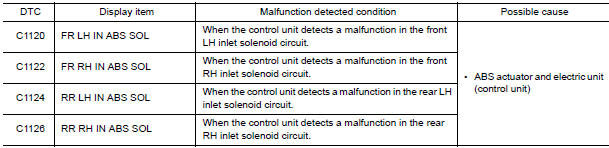
DTC CONFIRMATION PROCEDURE
1.CHECK SELF-DIAGNOSIS RESULTS
Check the self-diagnosis results.

Diagnosis Procedure
1.CONNECTOR INSPECTION
- Turn ignition switch OFF.
- Disconnect ABS actuator and electric unit (control unit) connector.
- Check terminals for deformation, disconnection, looseness, and so on. If any malfunction is found, repair or replace terminals.
- Reconnect connector and perform self-diagnosis
2.CHECK SOLENOID AND ACTUATOR RELAY POWER SUPPLY CIRCUIT
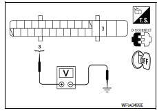
- Turn ignition switch OFF.
- Disconnect ABS actuator and electric unit (control unit) connector.
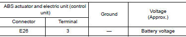
- Check voltage between ABS actuator and electric unit (control unit) connector E26 terminal 3 and ground.
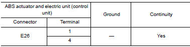
3. CHECK SOLENOID AND ACTUATOR RELAY GROUND CIRCUIT
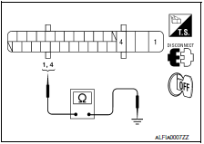
Check continuity between ABS actuator and electric unit (control unit) connector E26 terminals 1, 4 and ground.
Component Inspection
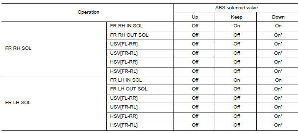
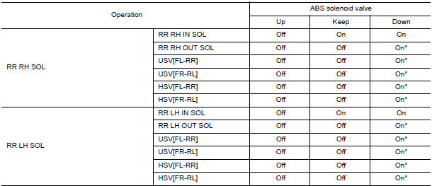
1.CHECK ACTIVE TEST
- Select each test menu item on "ACTIVE TEST".
- On the display, touch "Up", "Keep", and "Down", and check that the system operates as shown in the table below.
Special Repair Requirement
1.ADJUSTMENT OF STEERING ANGLE SENSOR NEUTRAL POSITION
Always perform the neutral position adjustment for the steering angle sensor, when replacing the ABS actuator and electric unit (control unit).
 C1116 stop lamp SW
Description
The stop lamp switch transmits the stop lamp switch signal (ON/OFF) to the
ABS actuator and electric unit
(control unit).
DTC Logic
DTC DETECTION LOGIC
DTC CONFIRMATION PROCEDU ...
 C1121, C1123, C1125, C1127 out ABS sol
Description
The solenoid valve increases, holds or decreases the fluid pressure of each
brake caliper according to the signals
transmitted by the ABS actuator and electric unit (control unit).
D ...
Other materials:
B2116 tilt motor
Description
The tilt motor is installed to the steering column assembly.
The tilt motor is activated with the automatic drive positioner control
unit.
The steering column is tilted up/down by changing the rotation direction
tilt motor.
DTC Logic
DTC DETECTION LOGIC
DTC No.
...
Illumination
Removal and Installation
TRUNK ROOM LAMP
Removal
Release the tab (A), then swing open the lens.
: Front
Remove the bulb (3).
Release the tab (B), then pull trunk room lamp (2) away from
body opening.
Disconnect the connector (1) and remove trunk room lamp
Installation
Install ...
Mechanical key
The Intelligent Key contains the mechanical key,
which can be used in case of a discharged battery.
To remove the mechanical key, release the lock
knob on the back of the Intelligent Key.
To install the mechanical key, firmly insert it into
the Intelligent Key until the lock knob return ...
Nissan Maxima Owners Manual
- Illustrated table of contents
- Safety-Seats, seat belts and supplemental restraint system
- Instruments and controls
- Pre-driving checks and adjustments
- Monitor, climate, audio, phone and voice recognition systems
- Starting and driving
- In case of emergency
- Appearance and care
- Do-it-yourself
- Maintenance and schedules
- Technical and consumer information
Nissan Maxima Service and Repair Manual

0.0063