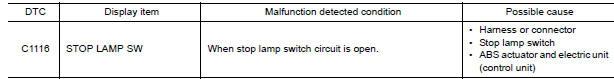
Nissan Maxima Service and Repair Manual: C1116 stop lamp SW
Description
The stop lamp switch transmits the stop lamp switch signal (ON/OFF) to the ABS actuator and electric unit (control unit).
DTC Logic
DTC DETECTION LOGIC
DTC CONFIRMATION PROCEDURE
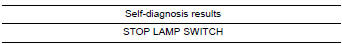
1.CHECK SELF-DIAGNOSIS RESULTS
Check the self-diagnosis results.
Diagnosis Procedure
1.CONNECTOR INSPECTION
- Disconnect stop lamp switch connector and ABS actuator and electric unit (control unit) connector.
- Check terminals for deformation, disconnection, looseness or damage.
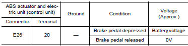
2.CHECK STOP LAMP SWITCH CIRCUIT
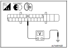
- Connect stop lamp switch connector.
- Check voltage between ABS actuator and electric unit (control unit) connector E26 terminal 20 and ground.
3.CHECK STOP LAMP SWITCH CIRCUIT FOR OPEN
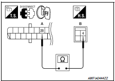
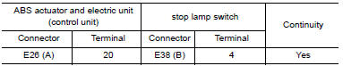
Check continuity between ABS actuator and electric unit (control unit) connector E26 (A) terminal 20 and stop lamp switch connector E38 (B) terminal 4.
4.CHECK STOP LAMP SWITCH CIRCUIT FOR SHORT
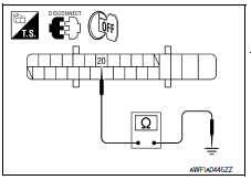
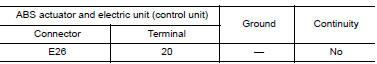
Check continuity between ABS actuator and electric unit (control unit) connector E26 terminal 20 and ground.
Special Repair Requirement
1.ADJUSTMENT OF STEERING ANGLE SENSOR NEUTRAL POSITION
Always perform the neutral position adjustment for the steering angle sensor, when replacing the ABS actuator and electric unit (control unit).
 C1115 ABS sensor [abnormal signal]
Description
When the sensor rotor rotates, the magnetic field changes. It converts the
magnetic field changes to current
signals (rectangular wave) and transmits them to the ABS actuator and elec ...
 C1120, C1122, C1124, C1126 in ABS sol
Description
The solenoid valve increases, holds or decreases the fluid pressure of each
brake caliper according to the signals
transmitted by the ABS actuator and electric unit (control unit).
D ...
Other materials:
Inspection and adjustment
REAR VIEW MONITOR POSSIBLE ROUTE LINE CENTER POSITION ADJUSTMENT
REAR VIEW MONITOR POSSIBLE ROUTE LINE CENTER POSITION ADJUSTMENT :
Description
Adjust the center position of the possible route line of the rear view
monitor if it is shifted.
REAR VIEW MONITOR POSSIBLE ROUTE LINE CENTER POSITIO ...
Audio antenna
Location of Antenna
AV control unit
AV control unit antenna feeder
In-line connectors M103, M501
Antenna amp.
Window antenna
Satellite radio antenna feeder
Satellite radio antenna
Window Antenna Repair
ELEMENT CHECK
Attach probe circuit tester (ohm setting) to antenna ...
Chassis and body maintenance
IN-CABIN MICROFILTER
IN-CABIN MICROFILTER : Removal and Installation
REMOVAL
Disengage the filter cover tab (1) by pushing up and pull out to
remove the filter cover.
Remove the in-cabin microfilter from the blower unit.
INSTALLATION
Installation is in the reverse order of removal ...
Nissan Maxima Owners Manual
- Illustrated table of contents
- Safety-Seats, seat belts and supplemental restraint system
- Instruments and controls
- Pre-driving checks and adjustments
- Monitor, climate, audio, phone and voice recognition systems
- Starting and driving
- In case of emergency
- Appearance and care
- Do-it-yourself
- Maintenance and schedules
- Technical and consumer information
Nissan Maxima Service and Repair Manual

0.0052