Nissan Maxima Service and Repair Manual: Power supply and ground circuit
AV CONTROL UNIT
AV CONTROL UNIT : Diagnosis Procedure
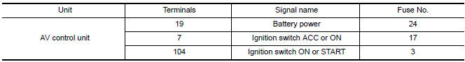
1.CHECK FUSES
Check that the following fuses of the AV control unit are not blown.
2.POWER SUPPLY CIRCUIT CHECK
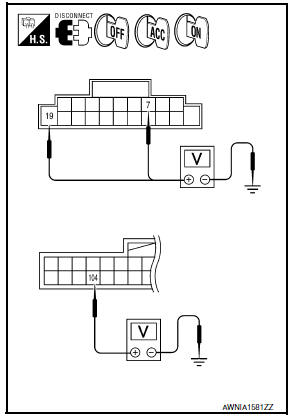
- Disconnect AV control unit connectors M152 and M156.
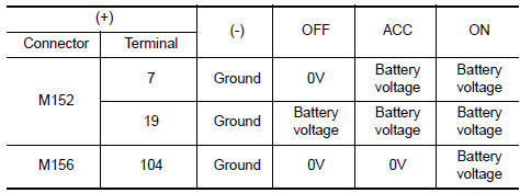
- Check voltage between the AV control unit connectors M152 and M156 and ground.
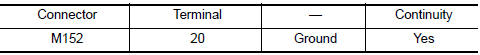
3.GROUND CIRCUIT CHECK
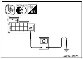
- Turn ignition switch OFF.
- Check continuity between AV control unit harness connector and ground.
DISPLAY UNIT
DISPLAY UNIT : Diagnosis Procedure
1.CHECK POWER SUPPLY CIRCUIT
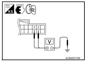
- Turn ignition switch to ACC.
- Check voltage between display unit harness connector M141 and ground.
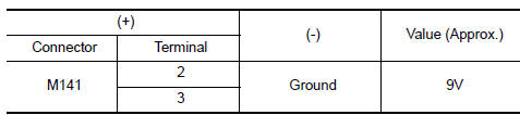
2.CHECK POWER SUPPLY CIRCUIT
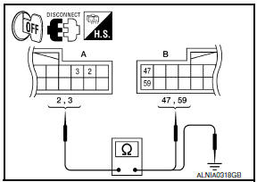
- Turn ignition switch OFF.
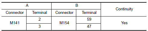
- Disconnect the display unit connector M141 and the AV control unit connector M154.
- Check continuity between the display unit harness connector M141 (A) and the AV control unit connector M154 (B).
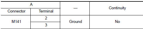
- Check continuity between the display unit harness connector M141 (A) and ground.
3.CHECK GROUND CIRCUIT
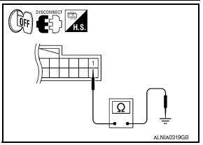
- Turn ignition switch OFF.
- Disconnect display unit connector.
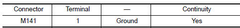
- Check continuity between display unit harness connector and ground.
A/C AND AV SWITCH ASSEMBLY
A/C AND AV SWITCH ASSEMBLY : Diagnosis Procedure
1.CHECK FUSE
Check that the fuse of the AC and AV switch assembly is not blown.

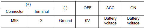
2.POWER SUPPLY CIRCUIT CHECK
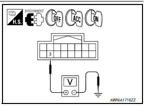
- Disconnect A/C and AV switch assembly connector M98.
- Check voltage between the A/C and AV switch assembly connector M98 and ground.
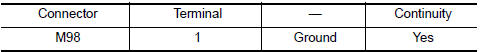
3.GROUND CIRCUIT CHECK
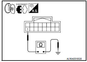
- Turn ignition switch OFF.
- Check continuity between A/C and AV switch assembly harness connector M98 and ground.
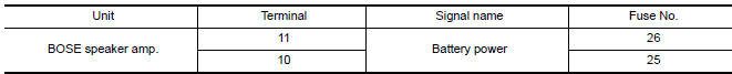
BOSE SPEAKER AMP
BOSE SPEAKER AMP : Diagnosis Procedure
1.CHECK FUSE
Check that the BOSE speaker amp. fuse is not blown
2.CHECK POWER SUPPLY CIRCUIT
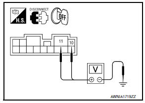
- Turn ignition switch OFF.
- Disconnect BOSE speaker amp. connector.
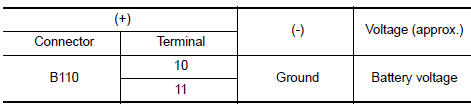
- Check voltage between BOSE speaker amp. harness connector B110 terminal 10, 11 and ground
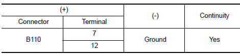
3.CHECK GROUND CIRCUIT
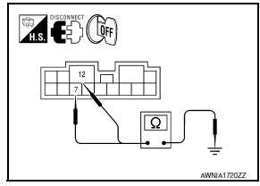
- Turn ignition switch OFF.
- Disconnect BOSE speaker amp. connector.
- Check continuity between BOSE speaker amp. harness connector B110 terminal 7,12 and ground.
SATELLITE RADIO TUNER
SATELLITE RADIO TUNER : Diagnosis Procedure
1.CHECK FUSES
Check that the following fuses of the satellite radio tuner (factory installed) are not blown.

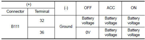
2.POWER SUPPLY CIRCUIT CHECK
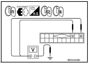
- Turn ignition switch OFF.
- Disconnect satellite radio tuner (factory installed) connector B111.
- Check voltage between the satellite radio tuner (factory installed) and ground.
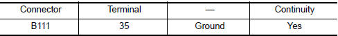
3.GROUND CIRCUIT CHECK
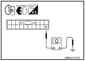
- Turn ignition switch OFF.
- Check continuity between satellite radio tuner (factory installed) harness connector and ground.
REAR VIEW CAMERA
REAR VIEW CAMERA : Diagnosis Procedure
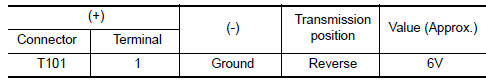
1.CHECK POWER SUPPLY CIRCUIT (REAR VIEW CAMERA SIDE)
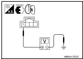
- Turn ignition switch ON.
- Shift transmission into Reverse.
- Check voltage between rear view camera harness connector T101 and ground
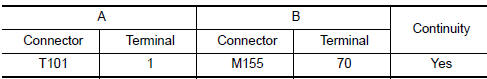
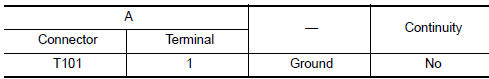
2.CHECK POWER SUPPLY CIRCUIT (CONTINUITY)
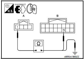
- Turn ignition switch OFF.
- Disconnect rear view camera and AV control unit connectors.
- Check continuity between rear view camera harness connector T101 (A) terminal 1 and AV control unit harness connector M155 (B) terminal 70.
- Check continuity between rear view camera harness connector T101 (A) terminal 1 and ground.
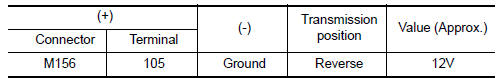
3.CHECK REVERSE POSITION INPUT SIGNAL
- Connect AV control unit connector.
- Turn ignition switch ON.
- Shift transmission into reverse.
- Check voltage between AV control unit harness connector M156 terminal 105 and ground.
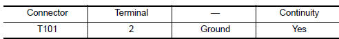
4.CHECK GROUND CIRCUIT
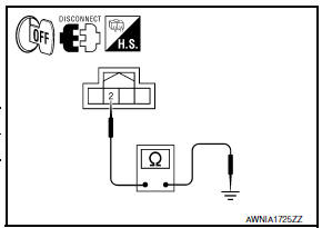
- Turn ignition switch OFF.
- Disconnect rear view camera harness connector.
- Check continuity between rear view camera harness connector T101 terminal 2 and ground.
BLUETOOTH CONTROL UNIT
BLUETOOTH CONTROL UNIT : Diagnosis Pro
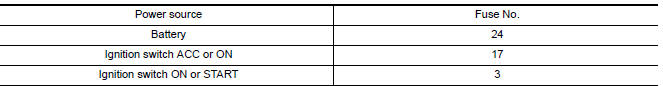
1.CHECK FUSE
Check that the following fuses of the Bluetooth control unit are not blown.
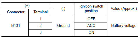
2.CHECK POWER SUPPLY CIRCUIT
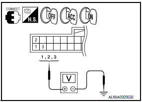
Check voltage between Bluetooth control unit harness connector B131 and ground
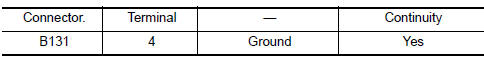
3.CHECK GROUND CIRCUIT
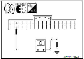
- Turn ignition switch OFF.
- Disconnect Bluetooth control unit connector.
- Check continuity between Bluetooth control unit harness connector B131 and ground.
MICROPHONE
MICROPHONE : Diagnosis Procedure
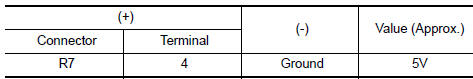
1.CHECK POWER SUPPLY CIRCUIT (MICROPHONE SIDE)
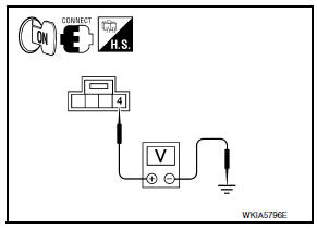
- Turn ignition switch ON.
- Check voltage between microphone harness connector R7 terminal 4 and ground
2.CHECK POWER SUPPLY CIRCUIT (CONTINUITY)
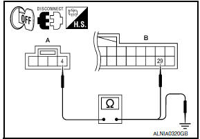
- Turn ignition switch OFF.
- Disconnect microphone and Bluetooth control unit harness connectors.
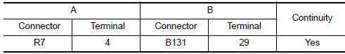
- Check continuity between microphone harness connector R7 (A) terminal 4 and Bluetooth control unit harness connector B131 (B) terminal 29.
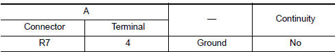
- Check continuity between microphone harness connector R7 (A) terminal 4 and ground.
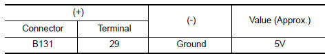
3.CHECK POWER SUPPLY CIRCUIT (BLUETOOTH CONTROL UNIT SIDE)
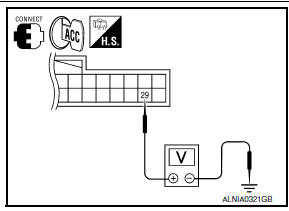
- Connect Bluetooth control unit harness connector.
- Turn ignition switch to ACC.
- Check voltage between Bluetooth control unit harness connector B131 terminal 29 and ground.
4.CHECK GROUND CIRCUIT
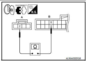
- Turn ignition switch OFF.
- Disconnect microphone harness connector R7 and Bluetooth control unit harness connector B131.
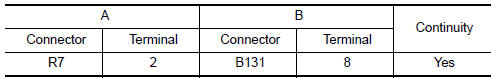
- Check continuity between microphone harness connector R7 (A) terminal 2 and Bluetooth control unit harness connector B131 (B) terminal 8.
 U1310 AV control unit
Description
DTC Logic
...
 RGB (R: red) signal circuit
Description
Transmit the image displayed with AV control unit with RGB signal to the
display unit.
Diagnosis Procedure
1.CHECK CONTINUITY RGB (R: RED) SIGNAL CIRCUIT
Turn ignition switch ...
Other materials:
Audio system
System Diagram
System Description
AUDIO SYSTEM
The audio system consists of the following components
AV control unit
Display unit
BOSE speaker amp.
Window antenna
Steering wheel audio control switches
A/C and AV switch assembly
Front door speakers
Tweeters
Center speaker
...
Cooling fan
Removal and Installation
Radiator cooling fan assembly
WARNING:
Do not remove the radiator cap when the engine is hot. Serious burns could occur
from high pressure
coolant escaping from the radiator. Wrap a thick cloth around the radiator cap.
Slowly turn it a quarter
turn to allow ...
ECM branch line circuit
Diagnosis Procedure
1.CHECK CONNECTOR
Turn the ignition switch OFF.
Disconnect the battery cable from the negative terminal.
Check the following terminals and connectors for damage, bend and
loose connection (unit side and connector
side).
- Models without automatic drive positione ...
Nissan Maxima Owners Manual
- Illustrated table of contents
- Safety-Seats, seat belts and supplemental restraint system
- Instruments and controls
- Pre-driving checks and adjustments
- Monitor, climate, audio, phone and voice recognition systems
- Starting and driving
- In case of emergency
- Appearance and care
- Do-it-yourself
- Maintenance and schedules
- Technical and consumer information
Nissan Maxima Service and Repair Manual

0.0069