Nissan Maxima Service and Repair Manual: Basic inspection
DIAGNOSIS AND REPAIR WORKFLOW
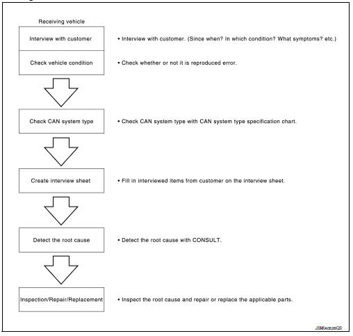
Trouble Diagnosis Flow Chart
Trouble Diagnosis Procedure
INTERVIEW WITH CUSTOMER Interview with the customer is important to detect the root cause of CAN communication system errors and to understand vehicle condition and symptoms for proper trouble diagnosis.
Points in interview
- What: Parts name, system name
- When: Date, Frequency
- Where: Road condition, Place
- In what condition: Driving condition/environment
- Result: Symptom
NOTE:
- Check normal units as well as error symptoms.
- Example: Circuit between ECM and the combination meter is judged normal if the customer indicates tachometer functions normally.
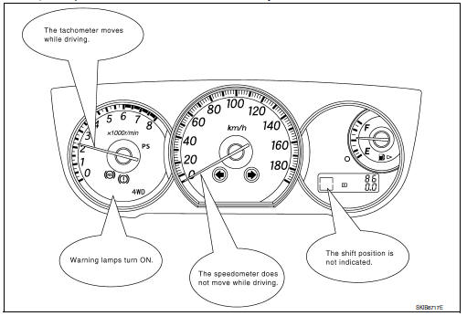
- When a CAN communication system error is present, multiple control units may malfunction or go into failsafe mode.
Indication of the combination meter is important to detect the root cause because it is the most obvious to the customer, and it performs CAN communication with many units.
INSPECTION OF VEHICLE CONDITION Check whether the symptom is reproduced or not.
NOTE: Do not turn the ignition switch OFF or disconnect the battery cable while reproducing the error. The error may temporarily correct itself, making it difficult to determine the root cause.
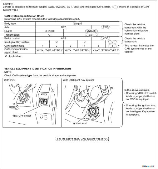
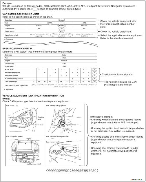
CHECK OF CAN SYSTEM TYPE (HOW TO USE CAN SYSTEM TYPE SPECIFICATION CHART) Determine CAN system type based on vehicle equipment.
NOTE:
- This chart is used if CONSULT does not automatically recognize CAN system type.
- There are two styles for CAN system type specification charts. Depending on
the number of available system types, either style A or style B may be used.
CAN System Type Specification Chart (Style A)
NOTE:
CAN system type is easily checked with the vehicle equipment identification information shown in the chart.
CAN System Type Specification Chart (Style B)
NOTE:
CAN system type is easily checked with the vehicle equipment identification information shown in the chart.
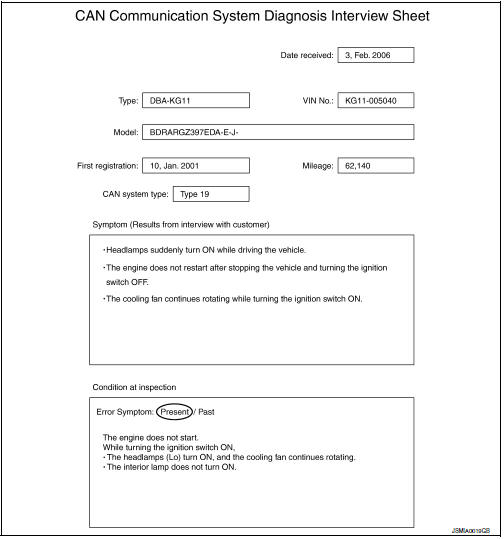
CREATE INTERVIEW SHEET
Fill out the symptom described by the customer, vehicle condition, and CAN system type on the interview sheet.
Interview Sheet (Example)
DETECT THE ROOT CAUSE CAN diagnosis function of CONSULT detects the root cause.
 Trouble diagnosis
Condition of Error Detection
DTC (e.g. U1000 and U1001) of CAN communication is indicated on SELF-DIAG
RESULTS on CONSULT if a
CAN communication signal is not transmitted or received between unit ...
 How to use this manual
HOW TO USE THIS SECTION
Caution
This section describes information peculiar to a vehicle and inspection
procedures.
For trouble diagnosis procedure, refer to LAN-15, "Trouble Diagnosis
Proc ...
Other materials:
Lock-up and select control system
System Diagram
System Description
The torque converter clutch piston in the torque converter is
engaged to eliminate torque converter slip to
increase power transmission efficiency.
The torque converter clutch control valve operation is controlled
by the torque converte ...
Periodic maintenance
FRONT SUSPENSION ASSEMBLY
Inspection and Adjustment
INSPECTION
Make sure the mounting conditions (looseness, backlash) of each component and
component conditions (wear, damage) are normal.
LOWER BALL JOINT END PLAY
Set front wheels in a straight-ahead position. Do not depress
brake peda ...
Navigation Swipe to Meter
Turn-by-turn route guidance can also be viewed
in the vehicle information display by using Navigation
Swipe to Meter. This can be done by
programming a route, touching the turn-by-turn
route icon on the center display, and swiping
towards the general direction of the vehicle information
di ...
Nissan Maxima Owners Manual
- Illustrated table of contents
- Safety-Seats, seat belts and supplemental restraint system
- Instruments and controls
- Pre-driving checks and adjustments
- Monitor, climate, audio, phone and voice recognition systems
- Starting and driving
- In case of emergency
- Appearance and care
- Do-it-yourself
- Maintenance and schedules
- Technical and consumer information
Nissan Maxima Service and Repair Manual

0.0066