Nissan Maxima Service and Repair Manual: Trouble diagnosis
Condition of Error Detection
DTC (e.g. U1000 and U1001) of CAN communication is indicated on SELF-DIAG RESULTS on CONSULT if a CAN communication signal is not transmitted or received between units for 2 seconds or more.
CAN COMMUNICATION SYSTEM ERROR
- CAN communication line open (CAN-H, CAN-L, or both)
- CAN communication line short (ground, between CAN communication lines, other harnesses)
- Error of CAN communication control circuit of the unit connected to CAN communication line WHEN DTC OF CAN COMMUNICATION IS INDICATED EVEN THOUGH CAN COMMUNICATION SYSTEM IS NORMAL
- Removal/installation of parts: Error may be detected when removing and installing CAN communication unit and related parts while turning the ignition switch ON. (A DTC except for CAN communication may be detected.)
- Fuse blown out (removed): CAN communication of the unit may cease.
- Voltage drop: Error may be detected if voltage drops due to discharged battery when turning the ignition switch ON (Depending on the control unit which carries out CAN communication).
- Error may be detected if the power supply circuit of the control unit, which carries out CAN communication, malfunctions (Depending on the control unit which carries out CAN communication).
- Error may be detected if reprogramming is not completed normally.
CAUTION:
CAN communication system is normal if DTC of CAN communication is indicated on SELF-DIAG RESULTS of CONSULT under the above conditions. Erase the memory of the self-diagnosis of each unit.
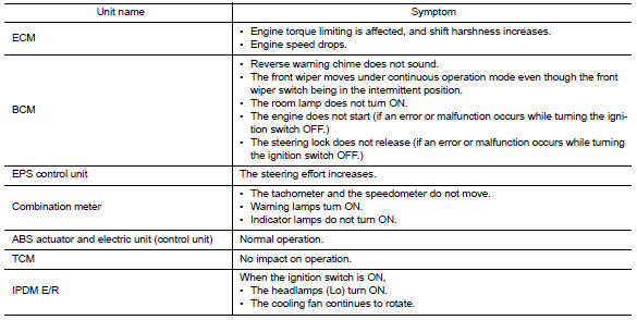
Symptom When Error Occurs in CAN Communication System
In CAN communication system, multiple units mutually transmit and receive signals. Each unit cannot transmit and receive signals if any error occurs on CAN communication line. Under this condition, multiple control units related to the root cause malfunction or go into fail-safe mode.
ERROR EXAMPLE
NOTE:
- Each vehicle differs in symptom of each unit under fail-safe mode and CAN communication line wiring.
- Refer to LAN-20, "Abbreviation List" for the unit abbreviation.
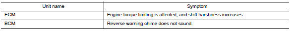
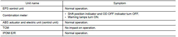
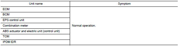
Example: TCM branch line open circuit
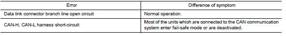
Example: Data link connector branch line open circuit
NOTE:
- When data link connector branch line is open, transmission and reception of CAN communication signals are not affected. Therefore, no symptoms occur. However, be sure to repair malfunctioning circuit.
- The model (all units on CAN communication system are Diag on CAN) cannot perform CAN diagnosis with CONSULT if the following error occurs. The error is judged by the symptom.
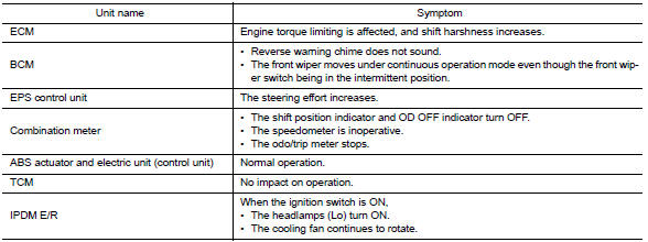
Example: Main Line Between Data Link Connector and ABS Actuator and Electric Unit (Control Unit) Open Circuit
Example: CAN-H, CAN-L Harness Short Circuit

CAN Diagnosis with CONSULT
CAN diagnosis on CONSULT extracts the root cause by receiving the following information.
- Response to the system call
- Control unit diagnosis information
- Self-diagnosis
- CAN diagnostic support monitor
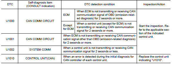
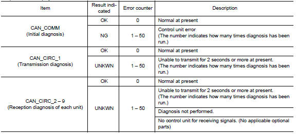
Self-Diagnosis
If communication signals cannot be transmitted or received among units communicating via CAN communication line, CAN communication-related DTC is displayed on the CONSULT "Self Diagnostic Result" screen.
NOTE:
The following table shows examples of CAN communication-related DTC. For other DTC, refer to the applicable sections.
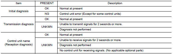
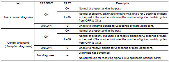
CAN Diagnostic Support Monitor
MONITOR ITEM (CONSULT)
Example: CAN DIAG SUPPORT MNTR indication
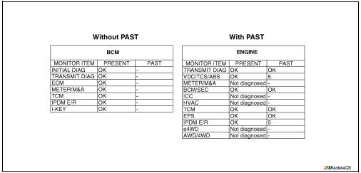
Without PAST
With PAST
MONITOR ITEM (ON-BOARD DIAGNOSIS)
NOTE:
For some models, CAN communication diagnosis result is received from the vehicle monitor.
Example: Vehicle Display
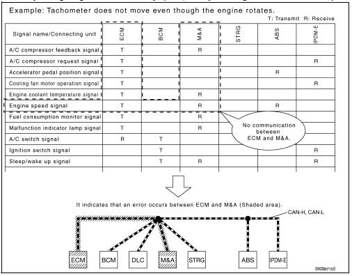
How to Use CAN Communication Signal Chart
The CAN communication signal chart lists the signals needed for trouble diagnosis. It is useful for detecting the root cause by finding a signal related to the symptom, and by checking transmission and reception unit.
 Diag on can
Description
"Diag on CAN" is a diagnosis using CAN communication instead of previous DDL1
and DDL2 communication
lines, between control units and diagnosis unit.
System Diagram
...
 Basic inspection
DIAGNOSIS AND REPAIR WORKFLOW
Trouble Diagnosis Flow Chart
Trouble Diagnosis Procedure
INTERVIEW WITH CUSTOMER
Interview with the customer is important to detect the root cause of CAN
communi ...
Other materials:
Automatic drive positioner (if so equipped)
The automatic drive positioner system has three
features:
Memory storage function (Key-link)
Memory storage function (Switch)
Entry/exit function
Key-link, when enabled, automatically retains the
driver's last seat, automatic steering wheel, and
outside mirror positions for that specif ...
Basic inspection
DIAGNOSIS AND REPAIR WORKFLOW
Trouble Diagnosis Flow Chart
Trouble Diagnosis Procedure
INTERVIEW WITH CUSTOMER
Interview with the customer is important to detect the root cause of CAN
communication system errors and to
understand vehicle condition and symptoms for proper trouble diagnosis ...
Symptom diagnosis
REFRIGERATION SYSTEM SYMPTOMS
WITH COLOR DISPLAY
WITH COLOR DISPLAY : Trouble Diagnoses for Abnormal Pressure
Whenever system′s high and/or low side pressure is abnormal, diagnose using a
manifold gauge. The marker above the gauge scale in the following tables
indicates the standard (us ...
Nissan Maxima Owners Manual
- Illustrated table of contents
- Safety-Seats, seat belts and supplemental restraint system
- Instruments and controls
- Pre-driving checks and adjustments
- Monitor, climate, audio, phone and voice recognition systems
- Starting and driving
- In case of emergency
- Appearance and care
- Do-it-yourself
- Maintenance and schedules
- Technical and consumer information
Nissan Maxima Service and Repair Manual

0.0071