Nissan Maxima Service and Repair Manual: How to use this manual
HOW TO USE THIS SECTION
Caution
- This section describes information peculiar to a vehicle and inspection procedures.
- For trouble diagnosis procedure, refer to LAN-15, "Trouble Diagnosis Procedure".
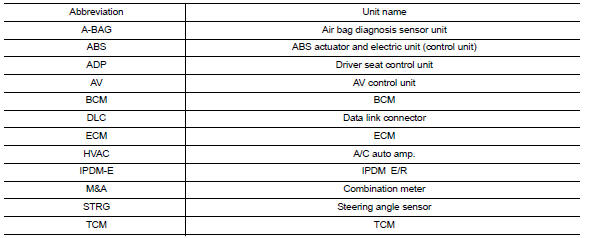
Abbreviation List
Unit name abbreviations in CONSULT CAN diagnosis and in this section are as per the following list.
 Basic inspection
DIAGNOSIS AND REPAIR WORKFLOW
Trouble Diagnosis Flow Chart
Trouble Diagnosis Procedure
INTERVIEW WITH CUSTOMER
Interview with the customer is important to detect the root cause of CAN
communi ...
 Precaution
PRECAUTIONS
Precaution for Supplemental Restraint System (SRS) "AIR BAG" and "SEAT BELT
PRE-TENSIONER"
The Supplemental Restraint System such as "AIR BAG" and "SEAT BELT
PRE-TENSIONER", used alo ...
Other materials:
Remote keyless entry receiver
Removal and Installation
REMOVAL
Remove glove box assembly. Refer to IP-20, "Removal and
Installation".
Disconnect the harness connector from the remote keyless
entry receiver (1).
Remove the screw (a) and remote keyless entry receiver (1).
INSTALLATION
Installation ...
Air breather hose
Exploded View
Air cleaner case
Air breather hose
Transaxle assembly
Heater pipe
Clip
A. Paint mark
: Front
Removal and Installation
REMOVAL
Remove front air duct. Refer to EM-24, "Removal
and Installa ...
Main line between HVAC and A-bag circuit
Diagnosis Procedure
1.CHECK HARNESS CONTINUITY (OPEN CIRCUIT)
Turn the ignition switch OFF.
Disconnect the battery cable from the negative
terminal.
Disconnect the following harness connectors.
A/C auto amp.
Harness connectors M1 and ...
Nissan Maxima Owners Manual
- Illustrated table of contents
- Safety-Seats, seat belts and supplemental restraint system
- Instruments and controls
- Pre-driving checks and adjustments
- Monitor, climate, audio, phone and voice recognition systems
- Starting and driving
- In case of emergency
- Appearance and care
- Do-it-yourself
- Maintenance and schedules
- Technical and consumer information
Nissan Maxima Service and Repair Manual

0.0066