Nissan Maxima Service and Repair Manual: U1310 AV control unit
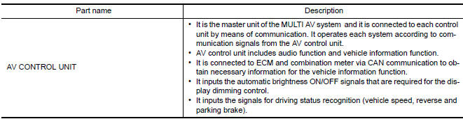
Description
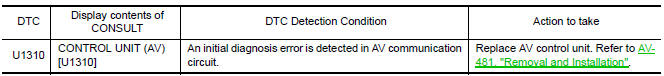
DTC Logic
 U1300 AV comm circuit
Description
U1300 is indicated when a communication signal malfunction occurs. U1300 is
indicated along with DTCs that
identify components connected to the AV control unit through communication
...
 Power supply and ground circuit
AV CONTROL UNIT
AV CONTROL UNIT : Diagnosis Procedure
1.CHECK FUSES
Check that the following fuses of the AV control unit are not blown.
2.POWER SUPPLY CIRCUIT CHECK
Disconnect AV cont ...
Other materials:
C1130, C1131, C1132, C1133, C1136 engine signal
Description
ABS actuator and electric unit (control unit) and ECM exchange the engine
signal with CAN communication
line.
DTC Logic
DTC DETECTION LOGIC
DTC CONFIRMATION PROCEDURE
1.CHECK SELF-DIAGNOSIS RESULTS
Check the self-diagnosis results.
Diagnosis Procedure
1.CHECK ENGINE S ...
Emission Control System Maintenance
Drive belts*:
Check engine drive belts for wear, fraying or
cracking and for proper tension. Replace any
damaged drive belts.
Engine air filter:
Replace at specified intervals. When driving for
prolonged periods in dusty conditions,
check/replace the filter more frequently.
Engine coolant*:
...
BCM (body control module)
Reference Value
NOTE:
The Signal Tech II Tool (J-50190) can be used to perform the
following functions. Refer to the Signal Tech II
User Guide for additional information.
Activate and display TPMS transmitter IDs
Display tire pressure reported by the TPMS transmitter
Read TPMS DTCs
R ...
Nissan Maxima Owners Manual
- Illustrated table of contents
- Safety-Seats, seat belts and supplemental restraint system
- Instruments and controls
- Pre-driving checks and adjustments
- Monitor, climate, audio, phone and voice recognition systems
- Starting and driving
- In case of emergency
- Appearance and care
- Do-it-yourself
- Maintenance and schedules
- Technical and consumer information
Nissan Maxima Service and Repair Manual

0.0054