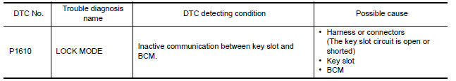
Nissan Maxima Service and Repair Manual: P1610 lock mode
Description
Performs ID verification through BCM and Intelligent Key when push-button ignition switch is pressed.
Prohibits the start of engine when an unregistered ID of Intelligent Key is used.
DTC Logic
DTC DETECTION LOGIC
DTC CONFIRMATION PROCEDURE
1.PERFORM DTC CONFIRMATION PROCEDURE
-
Insert Intelligent Key into the key slot.
-
Check "Self Diagnostic Result" with CONSULT.
2.PERFORM DTC CONFIRMATION PROCEDURE
-
Press the push-button ignition switch.
-
Check "Self Diagnostic Result" with CONSULT.
Diagnosis Procedure
Regarding Wiring Diagram information, refer to SEC-147, "Wiring Diagram".
1. INSPECTION START
Check the case in which DTC is detected.
-
Case1: It is detected when Intelligent Key is inserted into key slot.
-
Case2: It is detected after Intelligent Key is inserted into key slot and push-button ignition switch is pressed.
In which case is DTC detected?
Case1. GO TO 2
Case2. GO TO 4
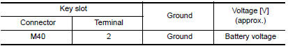
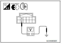
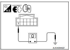
2.CHECK KEY SLOT INPUT SIGNAL
-
Turn ignition switch OFF.
-
Disconnect key slot harness connector.
-
Check voltage between key slot harness connector M40 terminal 2 and ground.
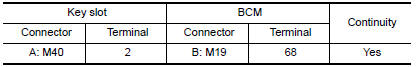
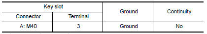
3.CHECK KEY SLOT CIRCUIT
-
Disconnect BCM harness connector.
-
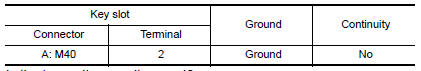
Check continuity between key slot harness connector M40 (A) terminal 2 and BCM harness connector M19 (B) terminal 68.
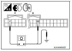
3. Check continuity between key slot harness connector M40 (A) terminal 2 and ground.
4.CHECK PUSH-IGNITION SWITCH OPERATION
Press push-button ignition switch and check if it turns ON.
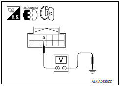
5.CHECK KEY SLOT COMMUNICATION SIGNAL
-
Turn ignition switch OFF.
-
Disconnect key slot harness connector.
-
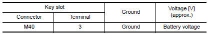
Check voltage between key slot harness connector M40 terminal 3 and ground.
6.CHECK KEY SLOT COMMUNICATION SIGNAL CIRCUIT
-
Disconnect BCM harness connector.
-
Check continuity between key slot harness connector M40 (A) terminal 3 and BCM harness connector M19 (B) terminal 69.
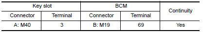
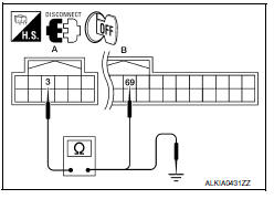
3. Check continuity between key slot harness connector M40 (A) terminal 3 and ground.
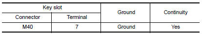
7.CHECK KEY SLOT GROUND CIRCUIT
-
Turn ignition switch OFF.
-
Disconnect key slot harness connector.
-
Check continuity between key slot harness connector M40 terminal 7 and ground.
8.CHECK INTERMITTENT INCIDENT
Refer to GI-41, "Intermittent Incident".
Inspection End.
 U1010 control unit (CAN)
DTC Logic
DTC DETECTION LOGIC
Diagnosis Procedure
1. REPLACE BCM
When DTC U1010 is detected, replace BCM.
Replace BCM. Refer to BCS-79, "Removal and
Installation". ...
 P1611 ID discord, IMMU-ECM
Description
BCM performs the ID verification with ECM that allows the
engine to start. Start the engine if the ID is OK.
ECM prevents the engine from starting if the ID is not registered. BCM st ...
Other materials:
Power generation voltage variable control system
System Diagram
System Description
Power generation variable voltage control system has been adopted. By varying
the voltage to the generator,
engine load due to power generation of the generator is reduced and fuel
consumption is decreased.
NOTE:
When any malfunction is detected in th ...
Automatic drive positioner control unit
Removal and Installation
REMOVAL
Remove audio unit. Refer to AV-73, "Removal and Installation"
(BASE AUDIO), AV-161, "Removal and Installation" (BOSE W/MONOCHROME
DISPLAY), AV-481, "Removal and Installation" (BOSE W/ COLOR DISPLAY),
AV-652, "Removal and Installation" (BOSE W/COLOR DISP ...
Intake valve timing control
System Diagram
System Description
INPUT/OUTPUT SIGNAL CHART
*: This signal is sent to the ECM via the CAN communication line
SYSTEM DESCRIPTION
This mechanism hydraulically controls cam phases continuously with the fixed
operating angle of the intake
valve.
The ECM receives s ...
Nissan Maxima Owners Manual
- Illustrated table of contents
- Safety-Seats, seat belts and supplemental restraint system
- Instruments and controls
- Pre-driving checks and adjustments
- Monitor, climate, audio, phone and voice recognition systems
- Starting and driving
- In case of emergency
- Appearance and care
- Do-it-yourself
- Maintenance and schedules
- Technical and consumer information
Nissan Maxima Service and Repair Manual

0.0058