Nissan Maxima Service and Repair Manual: U1010 control unit (CAN)
DTC Logic
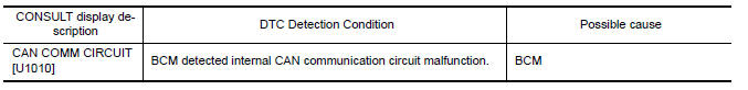
DTC DETECTION LOGIC
Diagnosis Procedure
1. REPLACE BCM
When DTC U1010 is detected, replace BCM.
Replace BCM. Refer to BCS-79, "Removal and Installation".
 U1000 CAN comm circuit
Description
CAN (Controller Area Network) is a serial communication
line for real time applications. It is an on-vehicle multiplex
communication line with high data communication speed and excell ...
 P1610 lock mode
Description
Performs ID verification through BCM and Intelligent Key
when push-button ignition switch is pressed.
Prohibits the start of engine when an unregistered ID of Intelligent Key is
us ...
Other materials:
Precaution
PRECAUTIONS
Precaution for Supplemental Restraint System (SRS) "AIR BAG" and
"SEAT BELT PRE-TENSIONER"
The Supplemental Restraint System such as "AIR BAG" and "SEAT BELT
PRE-TENSIONER", used along with a front seat belt, helps to reduce the risk
or severity of injury to the driver and front ...
Turn signal lamp circuit
Description
The BCM monitors inputs from the combination switch to determine when to
activate the turn signals. The BCM outputs voltage direction to the left and
right turn signals during turn signal operation or both during hazard warning
operation. The BCM sends a turn signal indicator requ ...
Mechanical key
The Intelligent Key contains the mechanical key,
which can be used in case of a discharged battery.
To remove the mechanical key, release the lock
knob on the back of the Intelligent Key.
To install the mechanical key, firmly insert it into
the Intelligent Key until the lock knob return ...
Nissan Maxima Owners Manual
- Illustrated table of contents
- Safety-Seats, seat belts and supplemental restraint system
- Instruments and controls
- Pre-driving checks and adjustments
- Monitor, climate, audio, phone and voice recognition systems
- Starting and driving
- In case of emergency
- Appearance and care
- Do-it-yourself
- Maintenance and schedules
- Technical and consumer information
Nissan Maxima Service and Repair Manual

0.0053