Nissan Maxima Service and Repair Manual: Oil Seal
Removal and Installation of Valve Oil Seal
REMOVAL
- Turn crankshaft until the cylinder requiring new oil seals is at TDC. This will prevent valve from dropping into cylinder. CAUTION: When rotating crankshaft, be careful to avoid scarring the front cover with the timing chain.
- Remove camshaft relating to valve oil seal to be removed. Refer to EM-76, "Removal and Installation".
- Remove valve lifters. Refer to EM-76, "Removal and Installation".
- Remove valve collet, valve spring retainer and valve spring using Tool. CAUTION: When working, take care not to damage valve lifter holes.
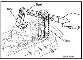
Tool numbers : KV10116200 (J-26336-A)
: KV10115900 (J-26336-20)
:
KV10109220 ( -
- Compress valve spring using Tool attachment, adapter.
Remove valve collet with magnet hand.
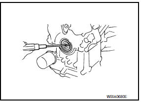
- Remove valve oil seal using Tool.
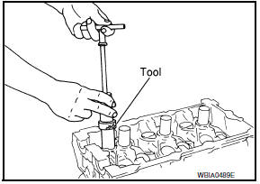
Tool number : KV10107902 (J-38959)
INSTALLATION
- Apply new engine oil to new valve oil seal joint surface and seal lip.
- Press in valve oil seal to height (H) using Tool to specified height.
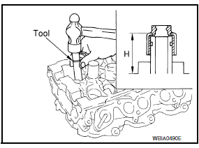
Tool number : - (J-39386)
NOTE: Dimension (H): height measured before valve spring seat installation.
Intake and exhaust : 14.3 - 14.9 mm (0.563 - 0.587 in)
- Installation of the remaining components is in the reverse order of removal.
Removal and Installation of Front Oil Seal
REMOVAL
- Remove engine under cover. Refer to EXT-15, "Exploded View".
- Remove drive belt. Refer to EM-14, "Removal and Installation".
- Remove radiator fan. Refer to CO-16, "Removal and Installation".
- Remove rear cover plate.
- Remove the crankshaft pulley as follows:
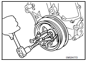
- Lock the drive plate using Tool.
Tool number : - (J-50288)
CAUTION: Do not damage the ring gear teeth, or the signal plate teeth behind the ring gear, when setting the Tool.
- Loosen crankshaft pulley and locate bolt seating surface at 10 mm (0.39 in) from its original position.
- Position a pulley puller at recess hole of crankshaft pulley to remove crankshaft pulley.
CAUTION: Do not use a puller claw on the outer diameter of the crankshaft pulley.
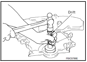
- Remove front oil seal from front cover using a suitable tool.
CAUTION: Be careful not to damage front cover or crankshaft.
INSTALLATION
- Apply new engine oil to new oil seal and install.
- Install new oil seal in the direction as shown.
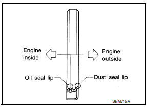
CAUTION: Press fit straight and avoid causing burrs or tilting the oil seal.
- Press-fit oil seal until it becomes flush with the timing chain case end face, using suitable tool.
- Make sure the garter spring in the oil seal is in position and seal lip is not inverted.
- Install crankshaft pulley and tighten the bolt in two steps.
- Lubricate thread and seat surface of the bolt with new engine oil.
- For the second step angle tighten using Tool.
Step 1 : 44.1 N*m (4.5 kg-m, 33 ft-lb)
Step 2 : 84 - 90 degrees
clockwise
Tool number : KV10112100 (BT-8653-A)
- Remove the Tool to unlock the drive plate.
Tool number : - (J-50288)
CAUTION: Do not damage the ring gear teeth, or the signal plate teeth behind the ring gear, when removing the Tool.
- Installation of the remaining components is in reverse order of removal.
Removal and Installation of Rear Oil Seal
REMOVAL
- Remove the upper oil pan. Refer to EM-37, "Removal and Installation (Upper Oil Pan)".
- Remove drive plate. Refer to EM-127, "Dowel Pin Alignment".
- Remove rear oil seal retainer using Tool.
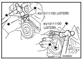
Tool Number : KV10111100 (J-37228)
CAUTION:
- Be careful not to damage mating surface.
- If rear oil retainer is removed, replace it with a new one
NOTE: Rear oil seal and retainer form a single part and are replaced as an assembly.
INSTALLATION
- Remove old liquid gasket material from mating surface of cylinder block and oil pan using a suitable scraper.
- Install the rear oil seal retainer using Tool (A).
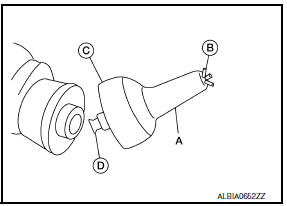
Tool number : - (J-47128)
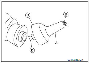
- Loosen the wing nut (B) on the end of the Tool (A).
- Insert the arbor (D) into the crankshaft pilot hole until the outer lip (C) of the Tool (A) covers the edge of the crankshaft sealing surface.
- Tighten the wing nut (B) to secure the Tool (A) to the crankshaft.
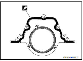
- Apply sealant to rear oil seal retainer as shown.
Use Genuine Silicone RTV Sealant, or equivalent. Refer to GI-21, "Recommended Chemical Products and Sealants".
CAUTION:
- Installation should be done within 5 minutes after applying liquid gasket.
- Do not fill the engine with oil for at least 30 minutes after the components are installed to allow the sealant to cure.
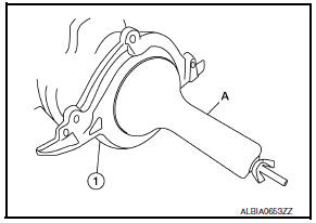
- Lubricate the sealing surface of the new rear main seal with new engine oil.
- Slide the new rear main seal (1) over the Tool (A) and onto the crankshaft.
- Loosen the wing nut and push the threaded rod into the handle to remove the Tool (A).
- Tighten the rear oil seal retainer bolts to specification.
- Install the piston to the connecting rod.
- Using suitable snap ring pliers, install the snap ring fully into the pin-groove of the piston rear side.
- Install the piston to the connecting rod.
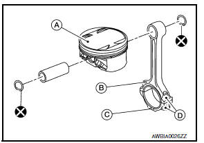
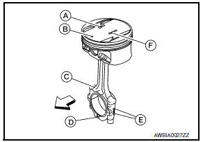
- Piston front mark
- Oil hole
- Connecting rod front mark
- Cylinder No.
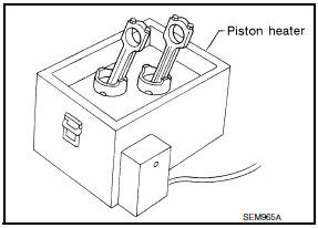
- Heat the piston until the piston pin can be pushed in by hand without
excess force [approx. 60 - 70C (140 to 158F)].
From the front to the rear, insert the piston pin into the piston and through the connecting rod.
WARNING: Pistons contain heat. When working, wear protective equipment to avoid getting burned.
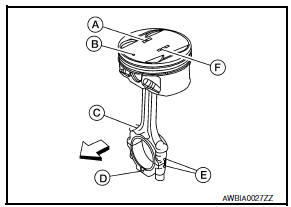
- Assemble so that the piston front mark (B) on the crown and the oil
hole (C), connecting rod front mark (D) and Cylinder No.
(E) on the are positioned as shown.
- Piston grade number
- Pin grade number
Engine front
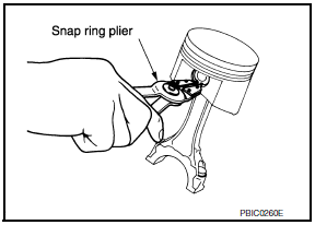
- Install the snap ring into the front of the piston pin-groove.
- After installing, check that the connecting rod pivots smoothly on the pin.
CAUTION: Do not reuse snap rings, always replace with new ones.
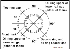
- Using a piston ring expander, install the piston rings.
CAUTION:
- Be careful not to damage the piston.
- When the piston rings are not replaced, remount the rings in their original positions.
- When replacing the piston rings, those without stamped surface (A) can be mounted either side up.
- Install the second ring with the stamped surface (B) facing upward. If the ring is not stamped it can face in either direction.
Top ring (A) : -
Second ring (B) : 2A
- Position each ring with the gap as shown, referring to the piston front mark.
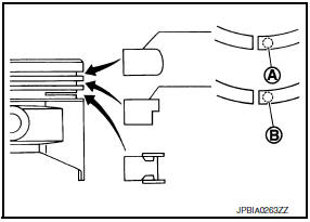
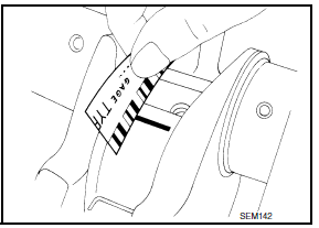
- Install the connecting rod bearings to the connecting rod and the connecting rod cap.
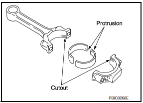
- When installing the connecting rod bearings, apply engine oil to the bearing surface (crankshaft side). Do not apply oil to the back surface (connecting rod and connecting rod cap side), but thoroughly clean it.
- When installing, align the connecting rod bearing protrusion with the notch of the connecting rod to install.
- Check that the oil holes on the connecting rod and on the corresponding bearing are aligned.
- Install the piston and connecting rod assembly into the corresponding cylinder.
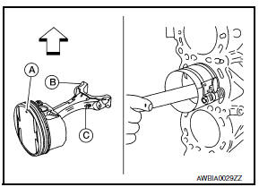
- Position the crankshaft pin corresponding to the connecting rod to be installed onto the bottom dead center.
- Apply engine oil sufficiently to the cylinder bore, piston, and crankshaft pin.
- Match the cylinder position with the cylinder No. (B) on the connecting rod to install.
- Install the piston with the piston front mark (A) on the crown
facing the front of the engine ( ) using a suitable tool.
- Oil hole (C)
CAUTION: Be careful not to damage the crankshaft pin and cylinder wall, resulting from interference of the connecting rod big end
- Install the connecting rod cap.
- Match the stamped cylinder number marks on the connecting rod with those on the cylinder cap for installation.
- Install the piston connecting rod assembly and cap so that the front mark on the cap and piston are facing the front of the engine.
- Lubricate the threads and seat surfaces with new engine oil.
- Check the connecting rod cap bolts before reusing, then install in their original position in the connecting rod. The bolts should screw in smoothly by hand.
- Measure the outer diameter of the connecting rod cap bolt as shown.
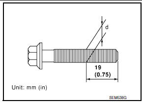
Outer diameter "d" of the connecting rod bolt
Standard : 7.90 - 8.00 mm
(0.3110 - 0.3150 in)
Limit : 7.75 mm (0.3051 in)
- Tighten the connecting rod nuts in two stages using Tool:
Stage 1 : 19 - 21 N*m (1.9 - 2.1 kg-m, 14 - 15 ft-lb)
Stage 2 : 90 -
95 degrees clockwise
CAUTION: Always use either an angle wrench or protractor. Avoid tightening based on visual check alone.
Tool number : KV10112100 (BT-8653-A)
- Apply engine oil to the threads and seats of the connecting rod bolts and nuts.
- After tightening the nuts, make sure that the crankshaft rotates smoothly.
- Check the connecting rod side clearance. If beyond the limit, replace the connecting rod and/or crankshaft.
Connecting rod side clearance:
Standard : 0.20 - 0.35 mm (0.0079 -
0.0138 in)
Limit : 0.40 mm (0.0157 in)
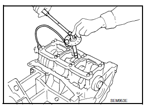
- Install the baffle plate to the main bearing beam.
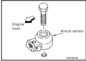
- Install the knock sensor.
- Make sure that there is no foreign material on the cylinder block mating surface and the back surface of the knock sensor.
- Install the knock sensor with the connector facing the rear of the engine.
- Do not tighten the bolts while holding the connector.
- Make sure that the knock sensor does not interfere with other parts.
CAUTION: If any impact by dropping occurs to the knock sensor, replace it with new one.
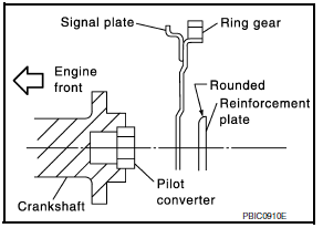
- Install the pilot converter with it's chamfer facing crankshaft as shown.
 : Crankshaft side
- Install the drive plate. Refer to EM-127, "Dowel Pin Alignment".
- Install the cylinder head. Refer to EM-90, "Removal and Installation".
- Install the timing chain. Refer to EM-64, "Removal and Installation".
- Install the oil pan. Refer to EM-37, "Removal and Installation (Upper Oil Pan)".
- Remove the engine from the stand and install the engine assembly into the vehicle. Refer to EM-103, "Removal and Installation".
- Assembly of the remaining parts is in the reverse order of disassembly.
CAUTION: Do not fill the engine with oil for at least 30 minutes after the components are installed to allow the sealant to cure.
INSPECTION AFTER INSTALLATION
- Before starting engine, check oil/fluid levels including engine coolant and engine oil. If less than required quantity, fill to the specified level. Refer to MA-15, "FOR USA AND CANADA : Fluids and Lubricants" (United States and Canada) or MA-16, "FOR MEXICO : Fluids and Lubricants" (Mexico).
- Use procedure below to check for fuel leakage.
- Turn ignition switch ON (with engine stopped). With fuel pressure applied to fuel piping, check for fuel leakage at connection points.
- Start engine. With engine speed increased, check again for fuel leakage at connection points.
- Run engine to check for unusual noise and vibration.
NOTE: If hydraulic pressure inside timing chain tensioner drops after removal and installation, slack in the guide may generate a pounding noise during and just after engine start. However, this is normal. Noise will stop after hydraulic pressure rises.
- Warm up engine thoroughly to make sure there is no leakage of fuel, exhaust gas, or any oils/fluids including engine oil and engine coolant.
- Bleed air from passages in lines and hoses, such as in cooling system.
- After cooling down engine, again check oil/fluid levels including engine oil and engine coolant. Refill to specified level, if necessary.
- Summary of the inspection items:
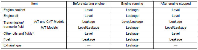
*Power steering fluid, brake fluid, etc.
Inspection
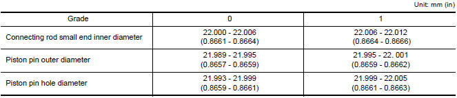
PISTON AND PISTON PIN CLEARANCE
Inner Diameter of Piston Pin Hole
- Measure the inner diameter of piston pin hole "dp".
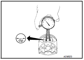
Standard diameter "dp"
Grade No. 0 : 21.993 - 21.999 mm (0.8659 - 0.8661
in)
Grade No. 1 : 21.999 - 22.005 mm (0.8661 - 0.8663 in)
Outer Diameter of Piston Pin
- Measure outer diameter of piston pin "Dp".
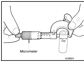
Standard diameter "Dp"
Grade No. 0 : 21.989 - 21.995 mm (0.8657 - 0.8659
in)
Grade No. 1 : 21.995 - 22.001 mm (0.8659 - 0.8662 in)
- Engine front
- Piston Grade No. (A)
- Piston front mark (B)
- Oil hole (C)
- Connecting rod front mark (D)
- Cylinder No. (E)
- Pin Grade No. (F)
Piston and Piston Pin Interference Fit
Standard Interference Fit = "Dp" - "dp"
Standard : 0.002 - 0.010 mm (0.0001 - 0.0004 in)
- If clearance exceeds specification, replace either or both the piston/piston pin assembly and connecting rod assembly with reference to specification of each part.
PISTON RING SIDE CLEARANCE
- Measure side clearance of piston ring and piston ring groove with feeler gauge.
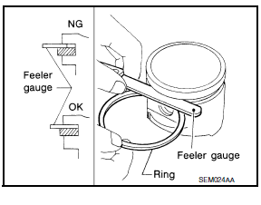
Standard Side Clearance
Top ring : 0.045 - 0.080 mm (0.0018 - 0.0031
in)
2nd ring : 0.030 - 0.070 mm (0.0012 - 0.0028 in)
Oil ring : 0.045
- 0.125 mm (0.0018 - 0.0049 in)
Maximum Limit
Top ring : 0.11 mm
(0.0043 in)
2nd ring : 0.1 mm (0.004 in)
Oil ring : -
- If out of specification, replace piston ring assembly. If clearance exceeds maximum limit with new rings, replace piston
PISTON RING END GAP
- Insert piston ring until it is in the middle of the cylinder bore and measure the end gap.
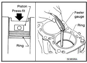
Standard
Top ring : 0.23 - 0.28 mm (0.0091 - 0.0110 in)
2nd ring :
0.33 - 0.43 mm (0.0130 - 0.0169 in)
Oil ring : 0.20 - 0.45 mm (0.0079 -
0.0177 in)
Limit:
Top ring : 0.50 mm (0.0197 in)
2nd ring : 0.62
mm (0.0244 in)
Oil ring : 0.80 mm (0.0315 in
- If out of specification, replace piston ring.
CONNECTING ROD BEND AND TORSION
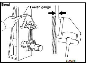
Bend : Limit 0.15 mm (0.0059 in) per 100 mm (3.94 in) length
Torsion
: Limit 0.30 mm (0.0118 in) per 100 mm (3.94 in) length
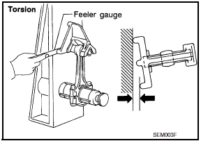
- If it exceeds the limit, replace connecting rod assembly.
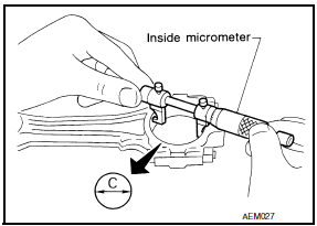
CONNECTING ROD BEARING HOUSING DIAMETER (BIG END)
- Install the connecting rod cap without the connecting rod bearing installed. After tightening the connecting rod nut to the specified torque, measure the connecting rod bearing housing big end inner diameter using an inside micrometer.
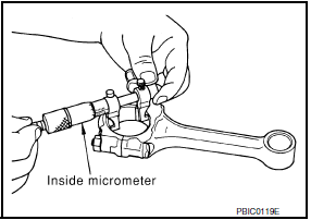
Standard : 55.000 - 55.013 mm (2.1654 - 2.1659 in
CONNECTING ROD BUSHING OIL CLEARANCE (SMALL END)
Inner Diameter of Connecting Rod (Small End)
- Measure inner diameter of piston pin bushing.
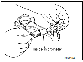
Standard Grade No. 0 : 22.000 - 22.006 mm (0.8661 - 0.8664 in)
Grade
No. 1 : 22.006 - 22.012 mm (0.8664 - 0.8666 in)
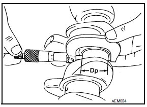
Outer Diameter of Piston Pin
- Measure outer diameter of piston pin.
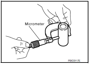
Standard Grade No. 0 : 21.989 - 21.995 mm (0.8657 - 0.8659 in) Grade
No. 1
: 21.995 - 22.001 mm (0.8659 -0.8662 in)
Connecting Rod Bushing Oil Clearance (Small End)
(Connecting rod small end oil clearance) = (Inner diameter of connecting rod small end) - (Outer diameter of piston pin)
Standard : 0.005 - 0.017 mm (0.0002 - 0.0007 in)
Limit : 0.030 mm
(0.0012 in)
- If the measured value exceeds the standard, replace the connecting rod assembly and/or piston and piston pin assembly.
- If replacing the piston and piston pin assembly, use the Table for Selective Fitting for Piston to select the piston corresponding to the applicable bore grade of the cylinder block to be used. Follow the "PISTON-TO-CYLINDER BORE CLEARANCE" procedure.
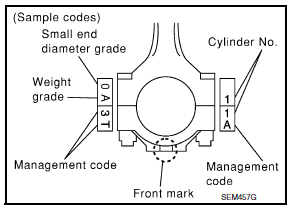
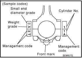
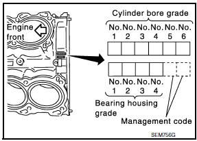
Factory installed parts grading:
- Engine front
- Piston Grade No. (A)
- Piston front mark (B)
- Oil hole (C)
- Connecting rod front mark (D)
- Cylinder No. (E)
- Pin Grade No. (F)
- Crown I.D. code (G)
Service parts apply only to grade 0.
CYLINDER BLOCK DISTORTION
- Using a scraper, remove any old gasket material on the cylinder block surface, and remove any oil, scale, carbon, or other contamination. CAUTION: Be careful not to allow gasket flakes to enter the oil or coolant passages.
- Measure the distortion on the block upper face at different points in six directions.
Distortion limit : 0.10 mm (0.0039 in
- If out of specification, resurface the cylinder block. The allowable amount of resurfacing is dependent on the amount of any cylinder head resurfacing. The resurfacing limit is [amount of cylinder head resurfacing] + [amount of cylinder head resurfacing] = 0.2 mm (0.008 in).
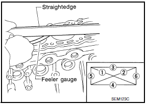
Cylinder block height : 214.95 - 215.05 mm (8.4626 - 8.4665 in)
INNER DIAMETER OF MAIN BEARING HOUSING
- Install the main bearing caps with the main bearings removed, and tighten the bolts to the specified torque.
- Using a bore gauge, measure the inner diameter of the main bearing housing "A".
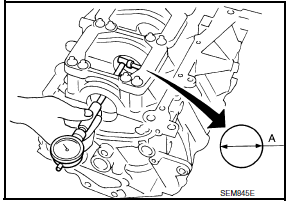
Standard : 63.993 - 64.017 mm (2.5194 - 2.5203 in)
- If out of the standard, replace the cylinder block and main bearing caps as an assembly. NOTE: These components cannot be replaced as a single unit, because they were processed together.
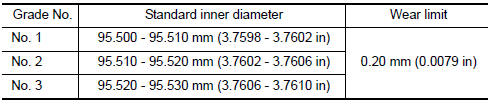
PISTON-TO-CYLINDER BORE CLEARANCE
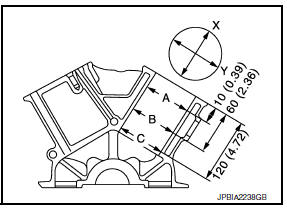
- Using a bore gauge, measure cylinder bore for wear, out-of-round and taper at (A), (B) and (C). The X axis is in the longitudinal direction of the engine.
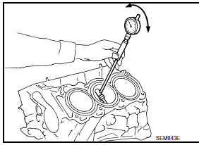
Cylinder bore inner diameter
If it exceeds the limit, rebore all cylinders. Replace cylinder block if necessary.
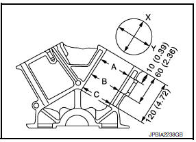
Out-of-round (Difference between X and Y) : limit 0.015 mm (0.0006
in)
Taper (Difference between A and C) : limit 0.010 mm (0.0004 in)
- Check for scratches and seizure. If seizure is found, hone it.
- If both cylinder block and piston are replaced with new ones, select piston of the same grade number punched on cylinder block rear position. These numbers are punched in either Arabic or Roman numerals.
- Measure piston skirt diameter.
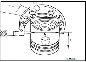
Piston diameter "A" : Refer to EM-135, "Cylinder Block".
Measuring
point "a" (Distance from the top) : 38.0 mm (1.496 in)
- Check that piston-to-bore clearance is within specification.
Piston-to-bore clearance at "B" : 0.010 - 0.030 mm (0.0004 - 0.0012 i
- The piston-to-bore clearance is measured at the "B" level in the cylinder as shown.
- Cylinder bore size is determined by adding piston-to-bore clearance to piston diameter "A".
Rebored size calculation : D = A + B − C where,
D : Bored diameter
A : Piston diameter as measured
B : Piston-to-bore clearance
C :
Honing allowance 0.02 mm (0.0008 in)
- Install main bearing caps, and tighten to the specified torque. Otherwise, cylinder bores may be distorted after boring.
- Cut cylinder bores.
- When any cylinder needs boring, all other cylinders must also be bored.
- Do not cut too much out of cylinder bore at a time. Cut only 0.05 mm (0.0020 in) or so in diameter at a time.
- Hone cylinders to obtain specified piston-to-bore clearance.
- Measure finished cylinder bore for out-of-round and taper.
- Measurement should be done after cylinder bore cools down.
CRANKSHAFT
- Check the crankshaft main and pin journals for scoring, wear, or cracks.
- Measure the journals for taper and out-of-round.
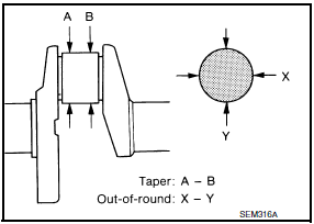
Standard
Out-of-round (X - Y) : 0.002 mm (0.0001 in)
Taper (A - B)
: 0.002 mm (0.0001 in)
- Measure crankshaft runout.
- Place a V-block on a precise flat table to support the journals on the both ends of the crankshaft.
- Place a dial gauge straight up on the No. 3 journal.
- While rotating the crankshaft, read the movement of the pointer on the dial gauge.
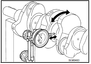
Runout limit (total indicator reading) : 0.10 mm (0.0039 in)
BEARING CLEARANCE
- Use either of the following two methods, however method "A" gives more reliable results and so is the preferred method.
Method A (Using Bore Gauge and Micrometer)
Main Bearing
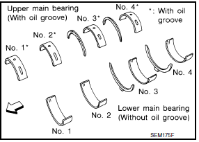
- Set the main bearings in their proper positions on the cylinder block and the main bearing cap.
- Install the main bearing caps and bearing beam to the cylinder block. Tighten all bolts in the numerical order as specified. Refer to EM-107, "Disassembly and Assembly".
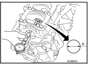
- Measure the inner diameters "A" of each main bearing as shown.
- Measure the outer diameters "Dm" of each crankshaft main journal as shown.
- Calculate the main bearing clearance.
Main bearing clearance = "A" - "Dm"
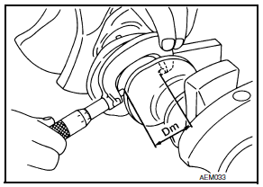
Standard : 0.012 - 0.022 mm (0.0005 - 0.0009 in)
Limit : 0.065 mm
(0.0026 in)
- If it exceeds the limit, replace the bearing.
- If clearance cannot be adjusted using any standard bearing grade, grind crankshaft journal and use an undersized bearing.
- When grinding the crankshaft journal, confirm that the "L" dimension in the fillet role is more than the specified limit.
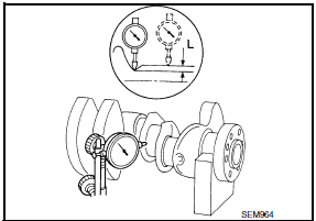
"L" : 0.10 mm (0.0039 in)
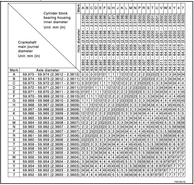
- If the crankshaft or the cylinder block is replaced with a new one, select thickness of the main bearings as follows:
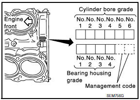
- The grade number of each cylinder block main journal is punched on the respective cylinder block. These numbers are punched in either Arabic or Roman numerals. If measured diameter is out of the grade punched, decide suitable grade from available main bearings.
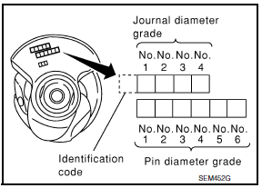
- The grade number of each crankshaft main journal is punched on the crankshaft end. These numbers are punched in either Arabic or Roman numerals. If measured diameter is out of grade punched, decide the suitable grade from available main bearings.
- Select the main bearing suitable thickness according to the following table:
Connecting Rod Bearing (Big End)
- Install the connecting rod bearing to the connecting rod and cap.
- Install the connecting rod cap to the connecting rod. Tighten to specification. Refer to EM-107, "Disassembly and Assembly".
- Measure the inner diameter "C" of each connecting rod (big end) as shown.
- Measure the outer diameter "Dp" of each crankshaft pin journal.
- Calculate the connecting rod bearing clearance.
Connecting rod bearing clearance = C - Dp
Standard : 0.020 - 0.045 mm (0.0008 - 0.0018 in)
Limit : 0.070 mm
(0.0028 in)

- If the calculated clearance exceeds the specified limit, replace the bearings.
- If the clearance cannot be adjusted within the standard of any bearing, grind the crankshaft journal and use undersized bearings.
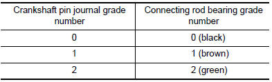
- If the crankshaft is replaced with a new one, select the connecting rod bearings according to the following table: Connecting Rod Bearing Grade Number (Identification Color)
These numbers are punched in either Arabic or Roman numerals.
Method B (Using Plastigage)
- Remove oil and dust on the crankshaft pin and the surfaces of each bearing completely.
- Cut a Plastigage slightly shorter than the bearing width, and place it in crankshaft axial direction, avoiding oil holes.
- Install the connecting rod bearings to the connecting rod cap, and tighten the connecting rod nuts to the specified torque.
CAUTION: Do not rotate the crankshaft.
- Remove the connecting rod cap and bearings, and using the scale on the Plastigage bag, measure the Plastigage width.
NOTE: The procedure when the measured value exceeds the repair limit is same as that described in "Method A (Using Bore Gauge and Micrometer)".
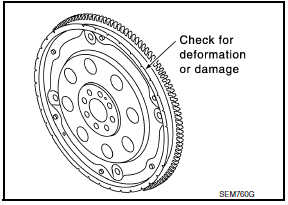
DRIVE PLATE RUNOUT
Use a suitable tool to measure the runout (Total Indicator Reading) as shown.
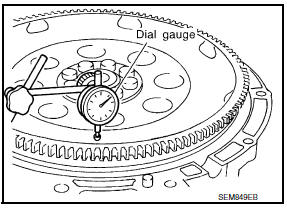
Drive plate torque converter surface : less than 0.35 mm (.0138
in)
Ring gear : less than 0.5 mm (.0197 in)
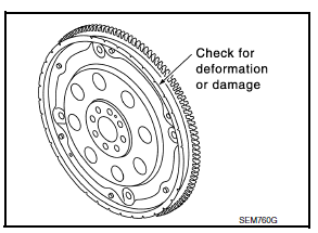
CAUTION:
- The signal plate is built into the drive assembly. Be careful not to damage the signal plate, particularly the teeth.
- Check the drive plate and signal plate for deformation or cracks.
- Keep all magnetized objects away from the signal plate, particularly the teeth.
OIL JET
- Check nozzle for deformation and damage.
- Blow compressed air from nozzle, and check for clogs.
- If it is not operating properly, replace oil jet.
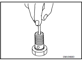
OIL JET RELIEF VALVE
- Using a clean plastic stick, press check valve in oil jet relief
valve.
Make sure that valve moves smoothly with proper reaction force.
- If it is not operating properly, replace oil jet relief valve.
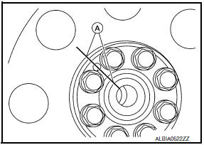
Dowel Pin Alignment
REMOVAL
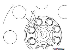
- Use suitable tool to lock the drive plate and match mark (A) the drive plate before removing the bolts.
CAUTION: Do not damage the ring gear teeth, or the signal plate teeth behind the ring gear.
- Remove drive plate.
- Loosen the drive plate in a diagonal order.
CAUTION:
- Do not place drive plate with signal plate facing down.
- When handling the signal plate, take care not to damage or scratch it.
- Handle the signal plate in a manner that prevents it from becoming magnetized.
INSTALLATION
Installation is in the reverse order of removal.
- When installing the drive plate to the crankshaft, use the match mark (A) as shown to correctly align the crankshaft side dowel pin to the drive plate side dowel pin hole.
- Install the drive plate and the reinforcement plate in the direction as shown.
- Tighten the drive plate bolts in a diagonal pattern in two steps. Refer to EM-107, "Disassembly and Assembly".
- Use a suitable tool to lock the drive plate.
 Camshaft
Exploded View
Camshaft position sensor bracket (RH)
Camshaft brackets
No. 1 camshaft bracket (RH)
Camshaft (EXH) (RH)
Camshaft (INT) (RH)
Cylinder head (RH)
Cylinder head (LH)
...
 Service Data And Specifications (SDS)
General Specification
GENERAL SPECIFICATIONS
Drive Belt
DRIVE BELT
Spark Plug
SPARK PLUG
*: Always check with the Parts Department for the latest parts information.
Intake Manifold
INT ...
Other materials:
Loading tips
The GVW must not exceed GVWR
or GAWR as specified on the
F.M.V.S.S./C.M.V.S.S. certification
label.
Do not load the front and rear axle to
the GAWR. Doing so will exceed the
GVWR.
WARNING
Properly secure all cargo with
ropes or straps to help prevent it
from sliding or shif ...
Front passenger air bag module
Removal and Installation
CAUTION:
Before servicing, turn ignition switch OFF, disconnect both
battery terminals and wait at least 3 minutes.
Do not use air tools or electric tools for servicing.
Always work from the side of air bag module. Do not work from
the front of it.
Always pl ...
Brake tube and hose
Hydraulic Circuit
Actuator
Master cylinder
Brake booster
Connector
Union bolt
18.2 N*m (1.9 kg-m, 13 ft-lb)
Flare nut M12
22.1 N*m (2.3 kg-m, 16 ft-lb)
Flare nut M10
16.2 N*m (1.7 kg-m, 12 ft-lb)
CAUTION:
All hoses and piping (tubes) must be free fr ...
Nissan Maxima Owners Manual
- Illustrated table of contents
- Safety-Seats, seat belts and supplemental restraint system
- Instruments and controls
- Pre-driving checks and adjustments
- Monitor, climate, audio, phone and voice recognition systems
- Starting and driving
- In case of emergency
- Appearance and care
- Do-it-yourself
- Maintenance and schedules
- Technical and consumer information
Nissan Maxima Service and Repair Manual

0.0071