Nissan Maxima Owners Manual: Difference between predicted and actual distances
The displayed guidelines and their locations on the ground are for approximate reference only.
Objects on uphill or downhill surfaces or projecting objects will be actually located at distances different from those displayed in the monitor relative to the guidelines (refer to illustrations). When in doubt, turn around and view the objects as you are backing up, or park and exit the vehicle to view the positioning of objects behind the vehicle.
Backing up on a steep uphill
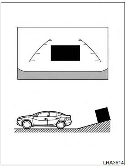
When backing up the vehicle up a hill, the distance guide lines and the vehicle width guide lines are shown closer than the actual distance.
Note that any object on the hill is further than it appears on the monitor.
Backing up on a steep downhill
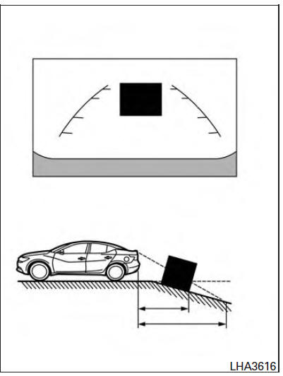
When backing up the vehicle down a hill, the distance guide lines and the vehicle width guide lines are shown farther than the actual distance.
Note that any object on the hill is closer than it appears on the monitor.
Backing up near a projecting object
The predicted course lines A do not touch the object in the display. However, the vehicle may hit the object if it projects over the actual backing up course.
Backing up behind a projecting object
The predicted course lines A do not touch the object in the display. However, the vehicle may hit the object if it projects over the actual backing up course.
Backing up behind a projecting object
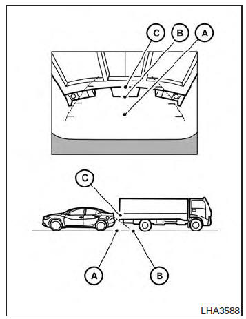
The position C is shown farther than the position B in the display. However, the position C is actually at the same distance as the position A .
The vehicle may hit the object when backing up to the position A if the object projects over the actual backing up course.
 Around View Monitor system operation
With the ignition switch in the ON position, move
the shift lever to the R (Reverse) position or press
the CAMERA button to operate the Around
View Monitor.
When the camera is first activated wi ...
 How to park with predicted course lines
WARNING
If the tires are replaced with different
sized tires, the predicted course lines
may be displayed incorrectly.
On a snow-covered or slippery road,
there may be a difference between the
p ...
Other materials:
Rear Timing Chain Case
Exploded View
Rear timing chain case
O-ring
Cylinder block
Removal and Installtion
CAUTION:
After removing timing chain, do not turn the crankshaft and
camshaft separately, or the valves will strike the pistons.
Before removing the upper oil pan, remove the crankshaft
posi ...
Hands-free phone system
System Diagram
System Description
Refer to the Owner's Manual for Bluetooth telephone system operating
instructions. NOTE: Cellular
telephones must have their wireless connection set up (paired) before using the
Bluetooth telephone system. Bluetooth telephone system allows users
who have ...
Thermostat and thermostat housing
Removal and Installation
Gasket
Thermostat assembly (water inlet)
WARNING:
Do not remove the radiator cap when the engine is hot. Serious burns could occur
from high pressure
engine coolant escaping from the radiator. Wrap a thick cloth around the
radiator cap. Slowly turn it a
...
Nissan Maxima Owners Manual
- Illustrated table of contents
- Safety-Seats, seat belts and supplemental restraint system
- Instruments and controls
- Pre-driving checks and adjustments
- Monitor, climate, audio, phone and voice recognition systems
- Starting and driving
- In case of emergency
- Appearance and care
- Do-it-yourself
- Maintenance and schedules
- Technical and consumer information
Nissan Maxima Service and Repair Manual

0.0055