Nissan Maxima Owners Manual: Around View Monitor system operation
With the ignition switch in the ON position, move the shift lever to the R (Reverse) position or press the CAMERA button to operate the Around View Monitor.
When the camera is first activated with the bird'seye view in the display, a red icon (if so equipped) will flash on the screen. This indicates that the sonar system (if so equipped) is activated. For additional information on the front and rear sonar system (if so equipped), refer to "Front and rear sonar system" in the "Starting and driving" section of this manual.
The screen displayed on the Around View Monitor will automatically return to the previous screen 3 minutes after the CAMERA button has been pressed with the shift lever in a position other than the R (Reverse) position.
Available views
WARNING
- The distance guide lines and the vehicle width lines should be used as a reference only when the vehicle is on a paved, level surface. The apparent distance viewed on the monitor may be different than the actual distance between the vehicle and displayed objects.
- Use the displayed lines and the bird'seye view as a reference. The lines and the bird's-eye view are greatly affected by the number of occupants, cargo, fuel level, vehicle position, road condition and road grade.
- If the tires are replaced with different sized tires, the predicted course lines and the bird's-eye view may be displayed incorrectly.
- When driving the vehicle up a hill, objects viewed in the monitor are further than they appear. When driving the vehicle down a hill, objects viewed in the monitor are closer than they appear.
- Objects in the rear view will appear visually opposite compared to when viewed in the monitor and outside mirrors.
- Use the mirrors or actually look to properly judge distances to other objects.
- On a snow-covered or slippery road, there may be a difference between the predicted course lines and the actual course line.
- The vehicle width and predicted course lines are wider than the actual width and course.
- The displayed lines will appear slightly off to the right, because the rear view camera is not installed in the rear center of the vehicle.
Front and rear view
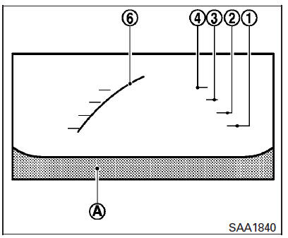
Front view
Guiding lines that indicate the approximate vehicle width and distance to objects with reference to the vehicle body line A are displayed on the monitor.
Distance guide lines
Indicate distances from the vehicle body:
- Red line 1 : approximately 1.5 ft (0.5 m)
- Yellow line 2 : approximately 3 ft (1 m)
- Green line 3 : approximately 7 ft (2 m)
- Green line 4 : approximately 10 ft (3 m)
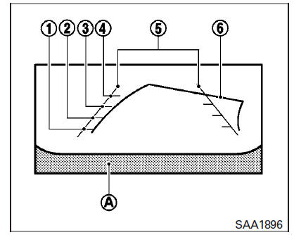
Rear view
Vehicle width guide lines 5 :
Indicate the approximate vehicle width when backing up.
Predicted course lines 6 :
Indicate the predicted course when operating the vehicle. The predicted course lines will be displayed on the monitor when the steering wheel is turned. The predicted course lines will move depending on how much the steering wheel is turned and will not be displayed while the steering wheel is in the straight-ahead position.
The front view will not be displayed when the vehicle speed is above 6 mph (10 km/h).
NOTE:
When the monitor displays the front view and the steering wheel turns about 90 degrees or less from the straight-ahead position, both the right and left predicted course lines 6 are displayed. When the steering wheel turns about 90 degrees or more, a line is displayed only on the opposite side of the turn.
Bird's-eye view
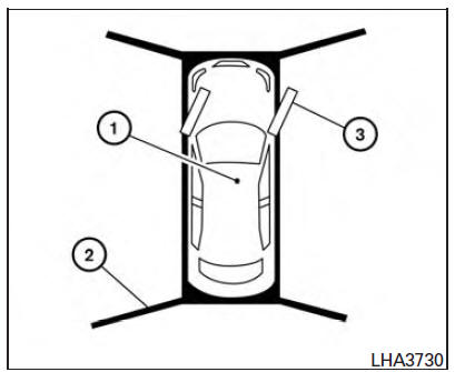
The bird's-eye view shows the overhead view of the vehicle, which helps confirm the vehicle position and the predicted course to a parking space.
The vehicle icon 1 shows the position of the vehicle. Note that the apparent distance between objects viewed in the bird's-eye view may differ somewhat from the actual distance to the vehicle.
The areas that the cameras cannot cover 2 are indicated in black.
The non-viewable area 2 is highlighted in yellow for several seconds after the bird's-eye view is displayed. It will be shown only the first time after the ignition switch is placed in the ON position.
The driver can check the approximate direction and angle of the tire on the display by the tire icon 3 when driving the vehicle forward or backward.
WARNING
- Objects in the bird's-eye view will appear further than the actual distance.
- Tall objects, such as a curb or vehicle, may be misaligned or not displayed at the seam of the views.
- Objects that are above the camera cannot be displayed.
- The view of the bird's-eye view may be misaligned when the camera position alters.
- A line on the ground may be misaligned and is not seen as being straight at the seam of the views. The misalignment will increase as the line proceeds away from the vehicle.
- Tire angle display does not indicate the actual tire angle.
Front-side view
Guiding lines
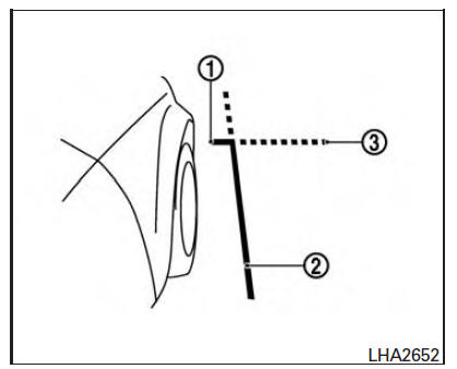
Guiding lines that indicate the approximate width and the front end of the vehicle are displayed on the monitor.
The front-of-vehicle line 1 shows the front part of the vehicle.
The side-of-vehicle line 2 shows the approximate vehicle width including the outside mirrors.
The extensions 3 of both the front 1 and side 2 lines are shown with a green dotted line.
 Around View Monitor (if so equipped)
1. CAMERA button
WARNING
Failure to follow the warnings and instructions
for the proper use of the
Around View Monitor system could
result in serious injury or death.
The Around View ...
 Difference between predicted and actual distances
The displayed guidelines and their locations on
the ground are for approximate reference only.
Objects on uphill or downhill surfaces or projecting
objects will be actually located at distances
...
Other materials:
Tire dressings
NISSAN does not recommend the use of tire
dressings. Tire manufacturers apply a coating to
the tires to help reduce discoloration of the rubber.
If a tire dressing is applied to the tires, it may
react with the coating and form a compound. This
compound may come off the tire while driving and ...
Checking tire pressure
1. Remove the valve stem cap from the
tire.
2. Press the pressure gauge squarely
onto the valve stem. Do not press too
hard or force the valve stem sideways,
or air will escape. If the hissing
sound of air escaping from the tire is
heard while checking the pressure,
reposition the gaug ...
ADP branch line circuit
Diagnosis Procedure
1.CHECK CONNECTOR
Turn the ignition switch OFF.
Disconnect the battery cable from the negative terminal.
Check the following terminals and connectors for damage, bend and
loose connection (unit side and connector
side).
Driver seat control unit
Harness connec ...
Nissan Maxima Owners Manual
- Illustrated table of contents
- Safety-Seats, seat belts and supplemental restraint system
- Instruments and controls
- Pre-driving checks and adjustments
- Monitor, climate, audio, phone and voice recognition systems
- Starting and driving
- In case of emergency
- Appearance and care
- Do-it-yourself
- Maintenance and schedules
- Technical and consumer information
Nissan Maxima Service and Repair Manual

0.0062