
Nissan Maxima Service and Repair Manual: B1065 - B1068, B1070 - B1073 passenger airbag module
Description
DTC B1065 - B1068, B1070 - B1073 PASSENGER AIR BAG MODULE
The passenger air bag module is dual stage and wired to the air bag diagnosis
sensor unit. The air bag diagnosis
sensor unit will monitor for opens and
shorts in detected lines to the passenger air bag module.
PART LOCATION
DTC Logic
DTC DETECTION LOGIC
With CONSULT
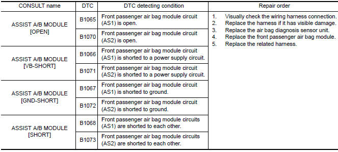
DTC CONFIRMATION PROCEDURE (With CONSULT)
1.CHECK SELF-DIAG RESULT
- Turn ignition switch ON.
- Check for DTC using CONSULT.
2.ERASE SELF-DIAG RESULT
Erase the DTC using CONSULT.
DTC CONFIRMATION PROCEDURE (Without CONSULT)
1.CHECK SELF-DIAG RESULT
- Turn ignition switch ON.
- Check the air bag warning lamp status. Refer to SRC-14, "Trouble
Diagnosis without CONSULT".
NOTE: SRS will not enter diagnosis mode if no malfunction is detected in user mode.
Diagnosis Procedure
1.HARNESS CONNECTOR
Visually inspect all applicable harness connectors for the following:
- Visible damage to connector or terminal
- Loose terminal
- Poor connection
NOTE:
All harness connectors should be
inspected from the air bag diagnosis sensor unit to the end component
(including any in-line connectors).
2.CONFIRM DTC
- Reconnect all harness connectors.
- Turn ignition switch ON.
- Check for DTC using CONSULT.
3.WIRING HARNESS
Check the wiring harness for visible damage.
NOTE:
The entire wiring harness should be inspected from the air bag diagnosis sensor
unit to the end component
(including any in-line connectors).
4.CONFIRM DTC
- Reconnect all harness connectors.
- Turn ignition switch ON.
- Check for DTC using CONSULT.
5.AIR BAG DIAGNOSIS SENSOR UNIT
- Replace the air bag diagnosis sensor unit. Refer to SR-31, "Removal and Installation".
- Turn ignition switch ON.
- Check for DTC using CONSULT.
6.FRONT PASSENGER AIR BAG MODULE
- Replace the front passenger air bag module. Refer to SR-17, "Removal and Installation".
- Turn ignition switch ON.
- Check for DTC using CONSULT.
7.RELATED HARNESS
Replace the related harness.
 B1049 - B1052, B1054 - B1057 driver airbag module
Description
DTC B1049 - B1052, B1054 - B1057 DRIVER AIRBAG MODULE
The driver air bag module is dual stage and wired to the air bag diagnosis
sensor unit through the spiral cable.The air bag diagno ...
 B1134 - B1137 side airbag module LH
Description
DTC B1134 - B1137 FRONT LH SIDE AIR BAG MODULE
The front LH side air bag module is wired to the air bag diagnosis sensor
unit. The air bag diagnosis sensorunit will monitor for opens a ...
Other materials:
Steering switch
Removal and Installation
REMOVAL
Remove the driver airbag module. Refer to SR-12, "Removal and
Installation".
Remove the steering wheel audio control switch screws (A).
Release the steering wheel audio control switch harness clips
(B).
Remove the steering wheel audio contr ...
P0456 evap control system
DTC Logic
DTC DETECTION LOGIC
NOTE:
If DTC P0456 is displayed with DTC P0442, first perform the trouble diagnosis
for DTC P0456.
This diagnosis detects very small leakage in the EVAP line between fuel tank
and EVAP canister purge volume
control solenoid valve, using the intake manifold va ...
C1145, C1146 yaw rate/side/decel G sensor
Description
The yaw rate/side/decel G sensor detects the yaw rate/side/decel G affecting
the vehicle, and transmits the
data to the ABS actuator and electric unit (control unit) as an analog voltage
signal.
DTC Logic
DTC DETECTION LOGIC
DTC CONFIRMATION PROCEDURE
1.CHECK SELF-DIAGNOSI ...
Nissan Maxima Owners Manual
- Illustrated table of contents
- Safety-Seats, seat belts and supplemental restraint system
- Instruments and controls
- Pre-driving checks and adjustments
- Monitor, climate, audio, phone and voice recognition systems
- Starting and driving
- In case of emergency
- Appearance and care
- Do-it-yourself
- Maintenance and schedules
- Technical and consumer information
Nissan Maxima Service and Repair Manual

0.0124