Nissan Maxima Service and Repair Manual: Wiring diagram
STARTING SYSTEM
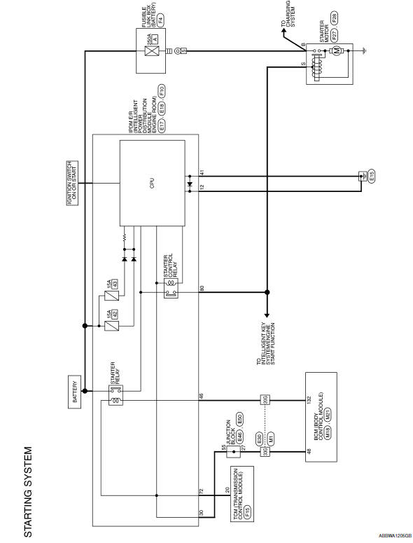
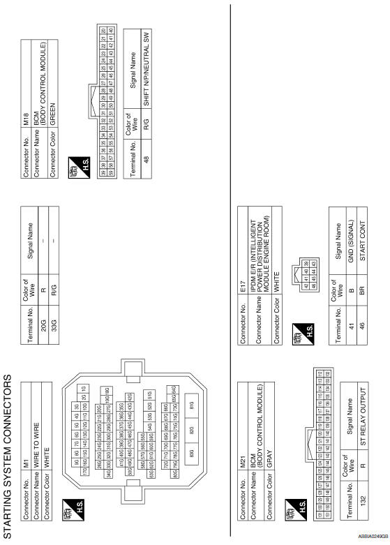
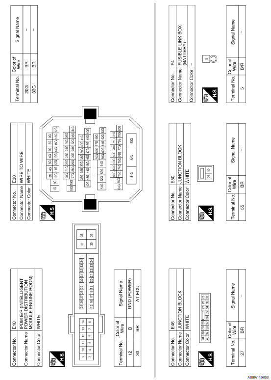
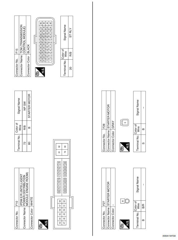
Wiring Diagram
 S connector circuit
Description
The starter motor magnetic switch is supplied with power when the ignition
switch is turned to the START position while the selector lever is in the P
or N position.
Diagnosis ...
 Symptom diagnosis
STARTING SYSTEM
Symptom Table
...
Other materials:
Starting the engine
1. Apply the parking brake.
2. Move the shift lever to P (Park) or N (Neutral).
P (Park) is recommended.
The starter is designed not to operate if
the shift lever is in any of the driving
positions.
3. Push the ignition switch to the ON position.
Depress the brake pedal and push the ign ...
B260f engine status
Description
BCM receives the engine status signal from ECM via CAN
communication.
DTC Logic
DTC DETECTION LOGIC
NOTE:
If DTC B260F is displayed with DTC
U1000, first perform the trouble diagnosis for DTC U1000. Refer to
SEC-29, "DTC Logic".
If DTC B260F is displayed with D ...
Diagnosis system (BCM)
DOOR LOCK
DOOR LOCK : CONSULT Function (BCM - DOOR LOCK)
SELF DIAGNOSTIC RESULT
DATA MONITOR
ACTIVE TEST
WORK SUPPORT
* : Initial setting
INTELLIGENT KEY
INTELLIGENT KEY : CONSULT Function (BCM - INTELLIGENT KEY)
DATA MONITOR
ACTIVE TEST
WORK SUPPORT
*: Initia ...
Nissan Maxima Owners Manual
- Illustrated table of contents
- Safety-Seats, seat belts and supplemental restraint system
- Instruments and controls
- Pre-driving checks and adjustments
- Monitor, climate, audio, phone and voice recognition systems
- Starting and driving
- In case of emergency
- Appearance and care
- Do-it-yourself
- Maintenance and schedules
- Technical and consumer information
Nissan Maxima Service and Repair Manual

0.0063