Nissan Maxima Service and Repair Manual: S connector circuit
Description
The starter motor magnetic switch is supplied with power when the ignition switch is turned to the START position while the selector lever is in the P or N position.
Diagnosis Procedure
CAUTION: Perform diagnosis under the condition that engine cannot start by the following procedure.
- Remove fuel pump fuse.
- Crank or start the engine (where possible) until the fuel pressure is released
1.CHECK "S" CONNECTOR CIRCUIT
- Turn ignition switch OFF.
- Disconnect starter motor connector F28.
- Shift CVT selector lever to "P" or "N" position.
- Check voltage between starter motor harness connector F28 terminal S and ground with the ignition in START.
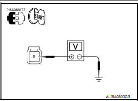
With ignition switch in START S - ground Battery voltage
2.CHECK CONNECTOR
- Turn ignition switch OFF.
- Check the following terminals and connectors for damage, bent pins and loose connections.
- IPDM E/R harness connector F10
- Starter motor harness connector F28
3.CHECK HARNESS CONTINUITY (OPEN/SHORT CIRCUIT)
- Disconnect the following harness connectors.
- IPDM E/R connector F10
- Starter motor connector F28
- Check continuity between starter motor harness connector F28 terminal S and IPDM E/R harness connector F10 terminal 80.
S - 80 Continuity ex
- Check continuity between starter motor harness connector F28 terminal S and ground.
S - ground Continuity does not exist
 B terminal C
Description
The "B" terminal is constantly supplied with battery power.
Diagnosis Procedure
CAUTION: Perform diagnosis under the condition that
the engine cannot start by the followin ...
 Wiring diagram
STARTING SYSTEM
Wiring Diagram
...
Other materials:
Intake Manifold
Removal and Installation
Intake manifold
Intake manifold gaskets
Refer to INSTALLATION
REMOVAL
WARNING: To avoid the danger of being
scalded, do not drain the coolant when the engine is hot.
Release the fuel pressure. Refer to EC-592, "Inspection".
Disconnect the ba ...
C1115 ABS sensor [abnormal signal]
Description
When the sensor rotor rotates, the magnetic field changes. It converts the
magnetic field changes to current
signals (rectangular wave) and transmits them to the ABS actuator and electric
unit (control unit).
DTC Logic
DTC DETECTION LOGIC
DTC CONFIRMATION PROCEDURE
1.CHECK ...
Performance test
Inspection
INSPECTION PROCEDURE
Connect recovery/recycling/recharging equipment (for HFC-134a) or
manifold gauge.
Start the engine, and set to the following condition.
Maintain test condition until A/C system becomes stable. (Approximately
10 minutes)
Check that test results ...
Nissan Maxima Owners Manual
- Illustrated table of contents
- Safety-Seats, seat belts and supplemental restraint system
- Instruments and controls
- Pre-driving checks and adjustments
- Monitor, climate, audio, phone and voice recognition systems
- Starting and driving
- In case of emergency
- Appearance and care
- Do-it-yourself
- Maintenance and schedules
- Technical and consumer information
Nissan Maxima Service and Repair Manual

0.0059