Nissan Maxima Service and Repair Manual: B terminal C
Description
The "B" terminal is constantly supplied with battery power.
Diagnosis Procedure
CAUTION: Perform diagnosis under the condition that the engine cannot start by the following procedure.
- Remove fuel pump fuse.
- Crank or start the engine (where possible) until the fuel pressure is depleted.
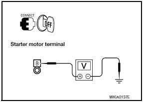
1.CHECK TERMINAL B POWER SUPPLY VOLTAGE
- Turn ignition switch OFF.
- Make sure that starter motor connector F27 terminal B connection is clean and tight.
- Check voltage between starter motor connector F27 terminal B and ground.

B - ground Battery voltage
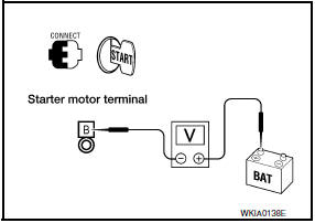
2.CHECK BATTERY CABLE (VOLTAGE DROP TEST)
- Shift CVT selector lever to "P" or "N" position.
- Check voltage between battery positive terminal and starter motor connector F27 terminal B while cranking the engine.

While cranking the engine Terminal B - B+ terminal Less than 0.5V
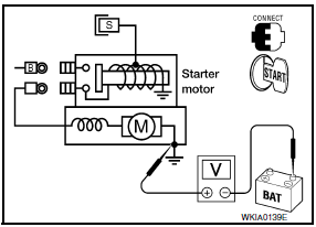
3.CHECK GROUND CIRCUIT STATUS (VOLTAGE DROP TEST)
- Shift CVT selector lever to "P" or "N" position.
- Check voltage between starter motor case and battery negative terminal while cranking the engine.

While cranking the engine Starter case - B- terminal Less
 S connector circuit
Description
The starter motor magnetic switch is supplied with power when the ignition
switch is turned to the START position while the selector lever is in the P
or N position.
Diagnosis ...
Other materials:
Cooling system
Cooling Circuit
Cylinder block (RH)
Oil cooler
Cylinder head (RH)
Water pump
Radiator
Water inlet
Thermostat
Cylinder head (LH)
Cylinder block (LH)
To heater
To electric throttle control actuator
From heater
From electric throttle control act ...
Operating range
The Intelligent Key functions can only be used
when the Intelligent Key is within the specified
operating range from the request switch 1 .
NOTE:
If all doors are already unlocked, opening
the trunk does NOT require an Intelligent
Key to be in range of the trunk request
switch or rear of ...
U0100 lost communication (ECM A)
DTC Logic
DTC DETECTION LOGIC
DTC CONFIRMATION PROCEDURE
1.PREPARATION BEFORE WORK
If another "DTC CONFIRMATION PROCEDURE" occurs just before, turn ignition
switch OFF and wait for at
least 10 seconds, then perform the next test.
2.PERFORM DTC CONFIRMATION PROCEDURE
Start the en ...
Nissan Maxima Owners Manual
- Illustrated table of contents
- Safety-Seats, seat belts and supplemental restraint system
- Instruments and controls
- Pre-driving checks and adjustments
- Monitor, climate, audio, phone and voice recognition systems
- Starting and driving
- In case of emergency
- Appearance and care
- Do-it-yourself
- Maintenance and schedules
- Technical and consumer information
Nissan Maxima Service and Repair Manual
0.0084

