Nissan Maxima Service and Repair Manual: TCM branch line circuit
Diagnosis Procedure
1.CHECK CONNECTOR
- Turn the ignition switch OFF.
- Disconnect the battery cable from the negative terminal.
- Check the following terminals and connectors for damage, bend and
loose connection (unit side and connector
side).
- TCM
- Harness connector F1
- Harness connector E3
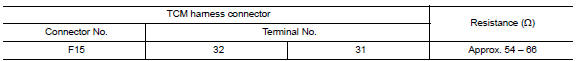
2.CHECK HARNESS FOR OPEN CIRCUIT
- Disconnect the connector of TCM.
- Check the resistance between the TCM harness connector terminals.
3.CHECK POWER SUPPLY AND GROUND CIRCUIT
Check the power supply and the ground circuit of the TCM. Refer to TM-126, "Wiring Diagram".
 ABS branch line circuit
Diagnosis Procedure
1.CHECK CONNECTOR
Turn the ignition switch OFF.
Disconnect the battery cable from the negative terminal.
Check the terminals and connectors of the ABS actuator and
elec ...
 IPDM-E branch line circuit
Diagnosis Procedure
1.CHECK CONNECTOR
Turn the ignition switch OFF.
Disconnect the battery cable from the negative terminal.
Check the terminals and connectors of the IPDM E/R for damage,
...
Other materials:
Diagnosis and repair work flow
Work Flow
OVERALL SEQUENCE
DETAILED FLOW
1.GET INFORMATION FOR SYMPTOM
Get the detailed information from the customer about the symptom
(the condition and the environment
when the incident/malfunction occurred) using the "Diagnostic Work Sheet".
(Refer to EC-12, "Diagnostic ...
Precaution
Precaution for Supplemental Restraint System (SRS) "AIR BAG" and "SEAT
BELT
PRE-TENSIONER"
The Supplemental Restraint System such as "AIR BAG" and "SEAT BELT PRE-TENSIONER",
used along
with a front seat belt, helps to reduce the risk or severity of injury to the
driver ...
P0500 VSS
Description
ECM receives vehicle speed signals from two different paths via CAN
communication line: One is from the
ABS actuator and electric unit (control unit) via the combination unit and the
other is from TCM.
DTC Logic
DTC DETECTION LOGIC
NOTE:
If DTC P0500 is displayed with ...
Nissan Maxima Owners Manual
- Illustrated table of contents
- Safety-Seats, seat belts and supplemental restraint system
- Instruments and controls
- Pre-driving checks and adjustments
- Monitor, climate, audio, phone and voice recognition systems
- Starting and driving
- In case of emergency
- Appearance and care
- Do-it-yourself
- Maintenance and schedules
- Technical and consumer information
Nissan Maxima Service and Repair Manual

0.0054